
1. Introduction and Overview
This manual provides comprehensive instructions for the installation, operation, and maintenance of the NUZEZCJG TCN7 Series Digital PID Temperature Controller. This device is designed for industrial applications requiring precise temperature regulation. Please read this manual thoroughly before installation and operation to ensure proper functionality and safety.
2. Product Features
- Large LCD display with clear white Process Value (PV) characters for easy readability.
- Advanced PID control algorithm for stable and accurate temperature management.
- Versatile output options: Relay and Solid State Relay (SSR) combined.
- Universal input compatibility for various sensor types.
- Integrated RS485 communication support for remote monitoring and control.
- SSR drive output (SSRP function) with control modes including ON/OFF, cycle control, and phase control.
- High-speed 50ms sampling rate ensuring rapid response.
- High display accuracy of ±0.3%.
- Compact and space-saving design for efficient panel integration.
- Two independent alarm outputs (ALM1, ALM2).
3. Technical Specifications
| Specification | Value |
|---|---|
| Model Variant | 72x72 4-20mA |
| Power Supply | 100-240VAC |
| Display Type | LCD |
| Display Size | 2.0 - 3.9 Inches |
| Output | Relay + SSR |
| Communication | RS485 |
| Sampling Rate | 50ms |
| Display Accuracy | ±0.3% |
| Alarm Outputs | ALM1, ALM2 |
| Usage Environment | Industrial |
| Cable Length | 1M (approximate) |
| Dimensions (Package) | 1.18 x 0.79 x 0.39 inches |
| Item Weight | 1.76 ounces (50 Grams) |
| Smart Device | No |
4. Safety Information
Adherence to safety guidelines is crucial for preventing injury and damage to the device. Always observe the following:
- Power Disconnection: Always disconnect all power to the controller and connected equipment before performing any installation, wiring, or maintenance.
- Proper Grounding: Ensure the controller is properly grounded according to local electrical codes and standards.
- Environmental Conditions: Do not operate the device in environments exceeding its specified temperature, humidity, or corrosive gas limits.
- Qualified Personnel: Installation and wiring should only be performed by qualified electricians or technicians.
- Wiring Integrity: Verify all wiring connections are secure and correct before applying power. Incorrect wiring can cause damage or fire.
- Ventilation: Ensure adequate ventilation around the controller to prevent overheating.
5. Setup and Installation
Careful installation and wiring are essential for the correct operation of the temperature controller.
5.1 Physical Installation
Mount the controller securely into a panel cutout of appropriate dimensions. Ensure sufficient space for wiring and ventilation at the rear of the unit.
5.2 Wiring Connections
Refer to the wiring diagram on the side of the unit and the terminal labels for correct connections. Ensure all wires are properly stripped and securely fastened to their respective terminals. Use appropriate wire gauges for power and load connections.

Figure 1: Rear view of the TCN7 Series controller, illustrating the terminal block for wiring connections.
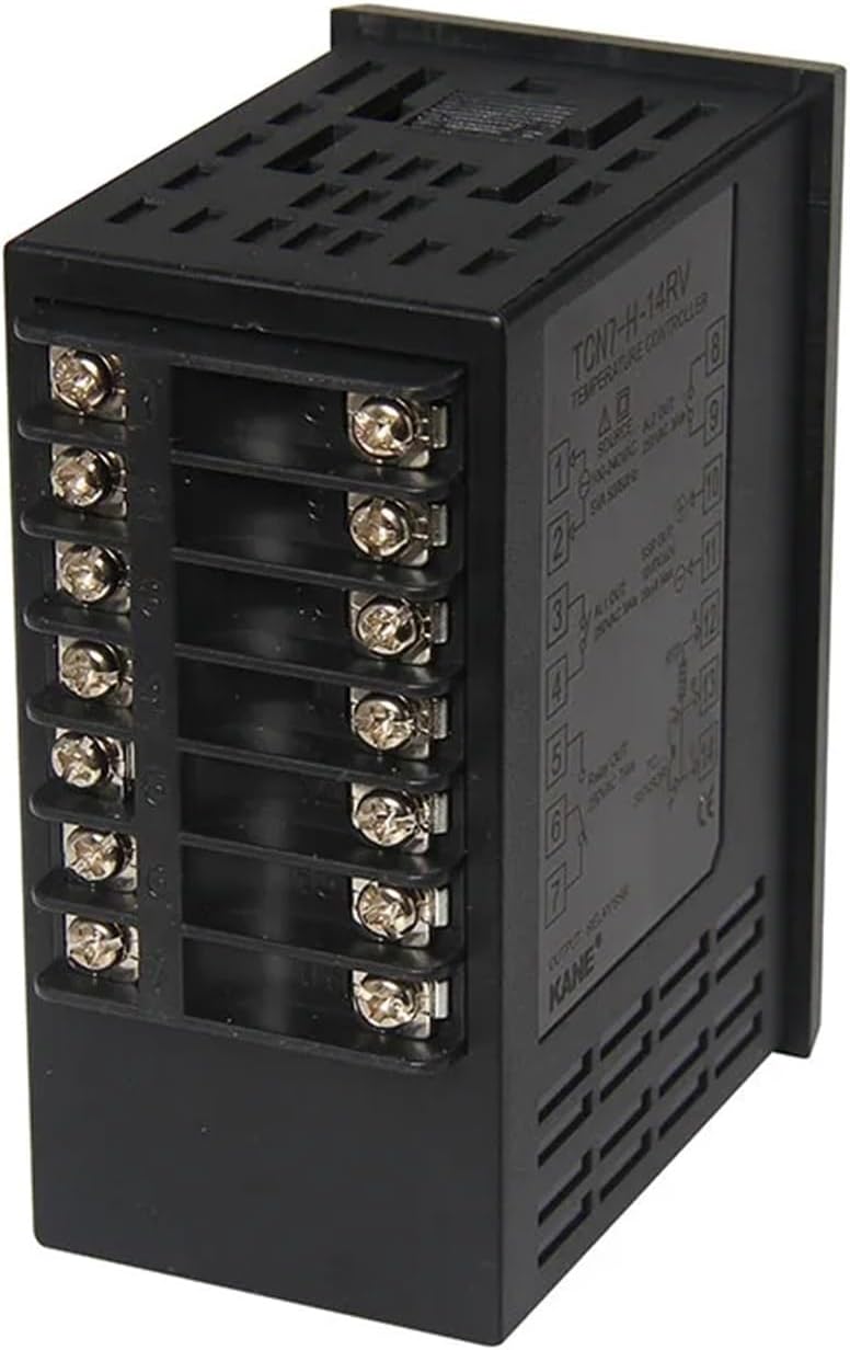
Figure 2: Side view of the TCN7 Series controller, showing specific wiring labels and connection points.
- Power Input: Connect the 100-240VAC power supply to the designated power terminals.
- Sensor Input: Connect your universal temperature sensor (e.g., thermocouple, RTD) to the sensor input terminals. Observe polarity for certain sensor types.
- Output Connections: Connect your heating/cooling elements to the Relay and/or SSR output terminals as required. Ensure the load current does not exceed the controller's specifications.
- RS485 Communication: Connect the RS485 A and B lines to the corresponding communication terminals for integration with a master device.
- Alarm Outputs: Connect external alarm indicators or devices to the ALM1 and ALM2 terminals if alarm functionality is desired.
5.3 Initial Power-Up
After verifying all connections, apply power to the controller. The LCD display will illuminate, showing the current Process Value (PV) and Set Value (SV).
6. Operating Instructions
The TCN7 Series controller features an intuitive LCD display and control buttons for easy operation.

Figure 3: Front view of the TCN7 Series controller, highlighting the LCD display and user interface buttons.
6.1 Display Overview
- PV (Process Value): Displays the current measured temperature from the sensor.
- SV (Set Value): Displays the target temperature set by the user.
- MV (Manipulated Value): Indicates the output power percentage or state.
- OUT1 Indicator: Illuminates when the primary output is active.
- °C Indicator: Shows the temperature unit (Celsius).
6.2 Setting the Set Value (SV)
- Press the SET button (often labeled with a 'P' or 'SET' icon) to enter the SV setting mode. The SV display will blink.
- Use the Up and Down arrow buttons to adjust the SV to the desired temperature.
- Press the SET button again to confirm the new SV and exit the setting mode.
6.3 Parameter Settings (Advanced)
To access advanced parameters for PID tuning, alarm settings, input type, and output modes, refer to the detailed parameter menu section in the full product manual (if available). Typically, this involves pressing and holding the SET button for several seconds to enter the parameter configuration menu. Navigate using arrow keys and confirm with the SET button.
- PID Parameters: Adjust Proportional band (P), Integral time (I), and Derivative time (D) values for optimal control performance.
- Alarm Settings: Configure alarm types (e.g., deviation, absolute) and set alarm thresholds for ALM1 and ALM2.
- Input Type: Select the correct sensor type (e.g., K-type thermocouple, Pt100 RTD) to match your connected sensor.
- Output Mode: Configure SSR drive output (SSRP function) for ON/OFF, cycle, or phase control as needed for your application.
7. Maintenance
Regular maintenance ensures the longevity and reliable operation of your temperature controller.
- Cleaning: Periodically clean the display and front panel with a soft, dry cloth. Do not use abrasive cleaners or solvents. Ensure no liquids enter the unit.
- Inspection: Regularly inspect wiring connections for looseness or signs of damage. Check for any physical damage to the controller casing.
- Ventilation: Ensure that ventilation openings are not obstructed to prevent internal heat buildup.
- Calibration: If precise temperature control is critical and deviations are suspected, consider professional calibration of the sensor and controller.
8. Troubleshooting
This section addresses common issues you might encounter with the TCN7 Series controller.
| Problem | Possible Cause | Solution |
|---|---|---|
| Display is blank | No power, incorrect wiring, or internal fault. | Check power supply and wiring connections. Ensure power is applied. If problem persists, contact support. |
| PV reading is incorrect or 'HHHH' / 'LLLL' displayed | Sensor disconnected, faulty sensor, incorrect input type setting, or sensor out of range. | Verify sensor wiring. Check sensor for damage. Ensure correct input type is selected in parameters. Confirm sensor operating range. |
| Output not activating | Incorrect SV, output mode setting, faulty output component, or wiring issue. | Check SV and ensure it's within operating range. Verify output mode (e.g., heating/cooling). Inspect output wiring and load. |
| Temperature oscillates widely | PID parameters not tuned correctly for the system. | Perform PID auto-tuning or manually adjust P, I, D parameters. Consult the full manual for tuning procedures. |
| RS485 communication failure | Incorrect wiring, address mismatch, baud rate mismatch, or software issue. | Verify RS485 A/B wiring. Check device address and baud rate settings. Ensure communication software is configured correctly. |
For issues not listed here or if troubleshooting steps do not resolve the problem, please contact NUZEZCJG customer support.
9. Warranty and Support
For information regarding product warranty, technical assistance, or service, please contact NUZEZCJG customer support through their official channels. Keep your purchase receipt or proof of purchase for warranty claims.