
1. Introduction
The ANKROYU NLQ3-125 Dual Power Automatic Transfer Switch is designed to automatically switch between two power sources, such as a main utility supply and a backup generator or photovoltaic system. This device ensures continuous power supply by seamlessly transferring the load when the primary power source fails or is restored. It supports both automatic and manual operation, performing transfers in milliseconds without requiring an external power supply. Constructed from PC flame retardant material, the switch is designed for durability and wear resistance, making it suitable for various applications.
This switch is suitable for a wide array of applications, including photovoltaic systems in homes, shopping malls, factories, laboratories, and farms.
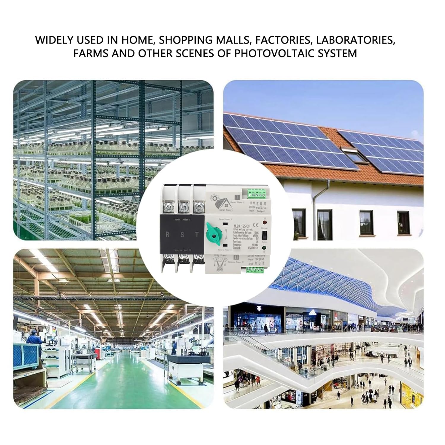
Figure 1: The NLQ3-125 switch is utilized in diverse environments such as industrial facilities, commercial centers, and residential settings with solar power.
2. Safety Information
Please read all safety instructions carefully before installation and operation. Failure to follow these instructions may result in electric shock, fire, or serious injury.
- Installation and maintenance must be performed by qualified electrical personnel only.
- Always disconnect all power sources before working on the switch or connected circuits.
- Ensure proper grounding of the electrical system.
- Do not operate the switch if it is damaged or appears to be malfunctioning.
- The maximum peripheral temperature should not exceed 40°C, and the minimum should not be lower than -5°C. The average temperature over 24 hours should not be higher than 35°C.
- The installation site altitude should not exceed 2000m.
- When the maximum temperature reaches 40°C, the relative humidity of the installation site should not exceed 50%. At lower temperatures, higher relative humidity is permissible (e.g., 90% at 25°C). Special measures should be taken to address occasional condensation on the product surface due to temperature changes.
3. Product Overview
The NLQ3-125 is a compact, DIN rail-mounted automatic transfer switch designed for reliable power management. It features clearly labeled terminals for main power sources (Normal Power A and Reverse Power B) and auxiliary control circuits. A manual/auto selector switch allows for flexible operation modes.
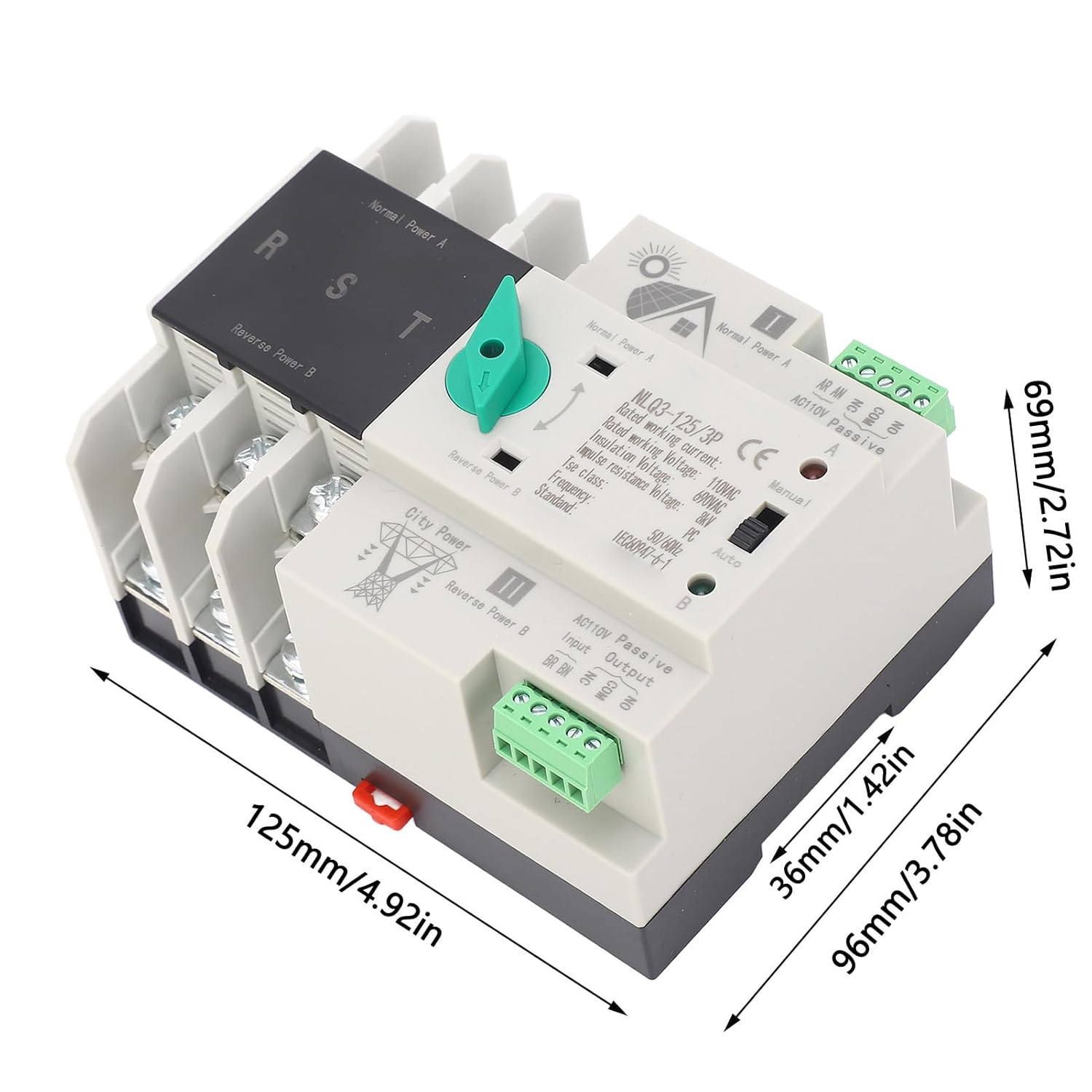
Figure 2: Front view of the NLQ3-125 switch, showing its compact design and key dimensions (125mm length, 96mm width, 69mm height).
Components:
- Main Power Terminals: Labeled 'Normal Power A' and 'Reverse Power B' for connecting primary and secondary power sources.
- Auxiliary Circuit Terminals: For control signals and status indication.
- Selector Switch: Allows selection between 'Manual' and 'Auto' operation modes.
- Indicators: LEDs to show the active power source (A or B).

Figure 3: Detail of the main power input/output terminals (R, S, T) for connecting primary and secondary power lines.

Figure 4: Detail of the AC110V Passive Input/Output terminals for auxiliary control circuits, including BR, BN, NC, COM, NO connections.

Figure 5: Close-up view of the manual/auto selector switch and the product's technical specifications printed on the casing.
4. Specifications
| Item Type | Dual Power Automatic Transfer Switch |
| Product Model | NLQ3-125, 3P |
| Material | PC Flame Retardant, Silver Alloy |
| Switch Type | Secondary Power Distribution |
| Rated Current | 63A |
| Rated Frequency | 50Hz, 60Hz |
| Electrical Level | PC Grade |
| Isolated Auxiliary Circuit | 2 Relays, each with two sets of contacts |
| Parcel Dimensions | 15 x 10 x 8 cm |
| Weight | 716 g |
| Manufacturer | ANKROYU |
5. Setup and Installation
Installation is simplified by a 35mm DIN rail mounting system, allowing for straightforward setup. Ensure all power is disconnected before beginning installation.
Installation Steps:
- Mounting: Securely attach the NLQ3-125 switch to a standard 35mm DIN rail within an appropriate electrical enclosure.
- Main Power Connection: Connect the primary power source (e.g., utility grid) to the 'Normal Power A' terminals. Connect the secondary power source (e.g., generator, solar inverter) to the 'Reverse Power B' terminals. Ensure correct phase and neutral connections.
- Auxiliary Circuit Connection: Connect any necessary control or indicator wiring to the auxiliary circuit terminals as per your system design.
- Verification: Double-check all connections for tightness and correctness before restoring power.

Figure 6: The NLQ3-125 switch mounted on a DIN rail inside a typical electrical distribution panel, alongside other circuit breakers.
6. Operating Instructions
The NLQ3-125 switch offers both automatic and manual modes of operation.
Automatic Mode:
- Set the selector switch to the 'Auto' position.
- In this mode, the switch will automatically detect the presence and stability of the primary power source (Normal Power A).
- If Normal Power A fails, the switch will automatically transfer the load to the secondary power source (Reverse Power B) within milliseconds.
- When Normal Power A is restored and stable, the switch will automatically transfer the load back to Normal Power A.
Manual Mode:
- Set the selector switch to the 'Manual' position.
- In this mode, the user can manually switch between Normal Power A and Reverse Power B using the green lever on the device.
- This mode is useful for testing or specific operational requirements where automatic transfer is not desired.
7. Maintenance
Regular maintenance helps ensure the longevity and reliable operation of your NLQ3-125 Dual Power Automatic Transfer Switch.
- Periodic Inspection: Annually inspect the switch for any signs of physical damage, loose connections, or discoloration.
- Cleaning: Keep the switch free from dust and debris. Use a dry, soft cloth for cleaning. Do not use liquid cleaners.
- Ventilation: Ensure that the electrical enclosure provides adequate ventilation to prevent overheating.
- Connection Checks: Periodically verify that all terminal connections are secure and tight.
8. Troubleshooting
If you encounter issues with your NLQ3-125 switch, consider the following basic troubleshooting steps:
- No Power Transfer: Check if both primary and secondary power sources are active and stable. Verify all main power connections.
- Incorrect Source Active: Ensure the selector switch is in the desired 'Auto' or 'Manual' position. If in 'Auto', check the status of both power sources.
- Indicators Not Working: Check the auxiliary circuit connections and ensure the switch is receiving power.
- Overheating: Ensure the switch is installed in a well-ventilated area and not overloaded beyond its rated current.
If problems persist after performing these checks, contact customer support or a qualified electrician.
9. Warranty and Support
The ANKROYU NLQ3-125 Dual Power Automatic Transfer Switch is manufactured by ANKROYU. For specific warranty details, please refer to the documentation provided at the time of purchase or contact your retailer.
For technical support, product inquiries, or assistance with troubleshooting, please contact the seller or visit the official ANKROYU store: