
1. Introduction
Thank you for purchasing the SIP Airmate Belt Drive Air Compressor. This manual provides essential information for the safe and efficient operation, maintenance, and troubleshooting of your compressor. Please read this manual thoroughly before operating the unit and keep it for future reference.
The SIP Airmate Belt Drive Air Compressor is a powerful and versatile unit designed for general work area applications in automotive, agricultural, and engineering settings. It features a 3hp / 2.2kW motor, a 50-liter receiver tank, and delivers 14CFM piston displacement for consistent air supply.
2. Safety Information
Always observe basic safety precautions to reduce the risk of fire, electric shock, and personal injury. Failure to follow these instructions may result in serious injury or property damage.
- Electrical Safety: Ensure the compressor is connected to a properly grounded 230V, 13A power supply. Do not operate in wet conditions.
- Pressure Safety: Never exceed the maximum operating pressure of 10 Bar (145psi). Do not tamper with the pressure relief valve.
- Noise Level: The compressor operates at 97 dB. Always wear appropriate hearing protection during operation.
- Moving Parts: Keep hands, hair, and loose clothing away from moving parts, especially the belt and fan.
- Ventilation: Operate the compressor in a well-ventilated area to prevent overheating.
- Drain Condensation: Regularly drain condensation from the air tank to prevent corrosion and maintain tank integrity.
3. Product Overview
Familiarize yourself with the main components of your SIP Airmate Belt Drive Air Compressor.

Figure 3.1: Overall view of the SIP Airmate Belt Drive Air Compressor, showing its main components including the motor, pump, air tank, and wheels.

Figure 3.2: Close-up view of the compressor pump head, highlighting the cooling fins and air intake filter.

Figure 3.3: Close-up view of the pressure gauges and air pressure regulator, used for monitoring and adjusting output pressure.

Figure 3.4: Close-up view of the quick-connect air outlets and the pressure switch, which controls the compressor's automatic on/off cycle.
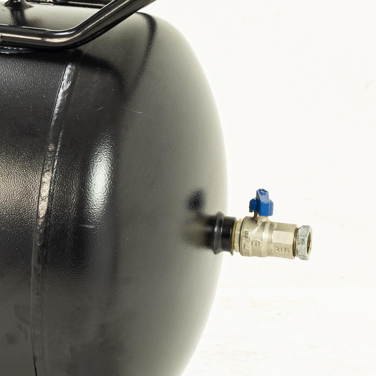
Figure 3.5: Close-up view of the tank drain valve located at the bottom of the air receiver, essential for draining condensed moisture.

Figure 3.6: Close-up view of the sturdy transport handle, designed for easy maneuverability of the compressor.

Figure 3.7: Close-up view of one of the robust transport wheels, facilitating movement across various surfaces.
4. Setup
- Unpacking: Carefully remove the compressor from its packaging. Inspect for any shipping damage.
- Wheel Assembly: Attach the wheels to the compressor frame using the provided hardware. Ensure they are securely fastened for stability and mobility.
- Handle Assembly: Secure the transport handle to the designated mounting points on the compressor.
- Initial Oil Check/Fill: This is an oil-lubricated compressor. Before first use, check the oil level using the dipstick or sight glass. If necessary, fill with appropriate compressor oil to the recommended level.
- Placement: Position the compressor on a firm, level surface in a clean, dry, and well-ventilated area. Allow at least 30cm of clearance around the unit for proper airflow.
- Electrical Connection: Connect the compressor to a dedicated 230V, 13A grounded electrical outlet. Do not use extension cords unless absolutely necessary, and if so, ensure it is rated for the compressor's power requirements.
5. Operating Instructions
- Starting the Compressor: Ensure the main power switch is in the 'OFF' position. Plug the compressor into the power outlet. Turn the main power switch to the 'ON' position. The compressor will begin to build pressure until it reaches its cut-out pressure.
- Adjusting Output Pressure: The compressor features two gauges: one for tank pressure and one for regulated output pressure. Use the red knob on the regulator to adjust the desired working pressure for your air tools. Turn clockwise to increase pressure, counter-clockwise to decrease.
- Connecting Air Tools: Attach your pneumatic air tool to one of the quick-connect air outlets. Ensure the connection is secure to prevent air leaks.
- Shutting Down: When finished, turn the main power switch to the 'OFF' position. Disconnect air tools and release any remaining pressure from the air hose.
- Draining Condensation: After each use, or at least daily, open the drain valve located at the bottom of the air tank to release accumulated moisture. This prevents corrosion inside the tank. Close the valve tightly once drained.
6. Maintenance
Regular maintenance is crucial for the longevity and safe operation of your compressor.
- Daily: Drain condensation from the air tank.
- Weekly/Every 10 Hours: Check oil level and top up if necessary. Inspect the air filter for dirt and clean or replace if clogged.
- Monthly/Every 50 Hours: Inspect the drive belt for wear, cracks, or proper tension. Adjust or replace as needed. Check all fasteners for tightness.
- Annually/Every 200 Hours: Change the compressor oil. Inspect the pressure relief valve for proper operation (pull ring to briefly release air).
- Cleaning: Keep the compressor clean and free of dust and debris, especially around the motor and pump cooling fins, to ensure efficient cooling.
- Storage: If storing for an extended period, drain the tank completely, change the oil, and store in a dry, protected area.
7. Troubleshooting
| Problem | Possible Cause | Solution |
|---|---|---|
| Compressor does not start | No power, tripped circuit breaker, faulty switch | Check power connection, reset breaker, contact service |
| Low air pressure/slow recovery | Air leak, clogged air filter, worn piston rings, loose belt | Check connections for leaks, clean/replace filter, inspect belt tension, contact service |
| Excessive noise/vibration | Loose components, worn bearings, low oil | Tighten fasteners, check oil level, contact service |
| Motor overheats | Poor ventilation, low voltage, prolonged use | Ensure adequate ventilation, check power supply, allow cool-down periods |
| Air in tank contains water | Condensation not drained regularly | Drain tank daily, ensure proper aftercooler function |
8. Specifications
| Specification | Value |
|---|---|
| Manufacturer | SIP |
| Part Number | SIP-06456 |
| Item Weight | 55 kg |
| Power Source | Corded Electric |
| Voltage | 230 Volts |
| Wattage | 2.2 KW |
| Amperage Capacity | 13 Amps |
| Maximum Power | 2.2 Kilowatts (3hp) |
| Air Flow Capacity | 14 Cubic Feet Per Minute (CFM) |
| Maximum Pressure | 10 Bars (145psi) |
| Sound Level | 97 dB |
| Special Features | Portable, Built-In Gauge, Heavy Duty, Quick Inflation |
| Included Components | User Manual |
9. Warranty and Support
This product comes with a user manual detailing its operation and maintenance. For specific warranty information, please refer to the documentation included with your purchase or contact SIP Industrial Products directly. For technical support or spare parts, please contact your authorized SIP dealer or visit the official SIP website.
Contact Information: Please refer to the contact details provided on the SIP website or in your purchase documentation for the most up-to-date support information.

