1. Introduction
This manual provides detailed instructions for the installation, operation, and maintenance of the GODIYMODULES Industrial USB to RS485 Converter. This device facilitates communication between a USB-enabled computer and RS485 devices, commonly used in industrial automation, data acquisition, and other serial communication applications. Please read this manual thoroughly before using the product to ensure proper functionality and safety.
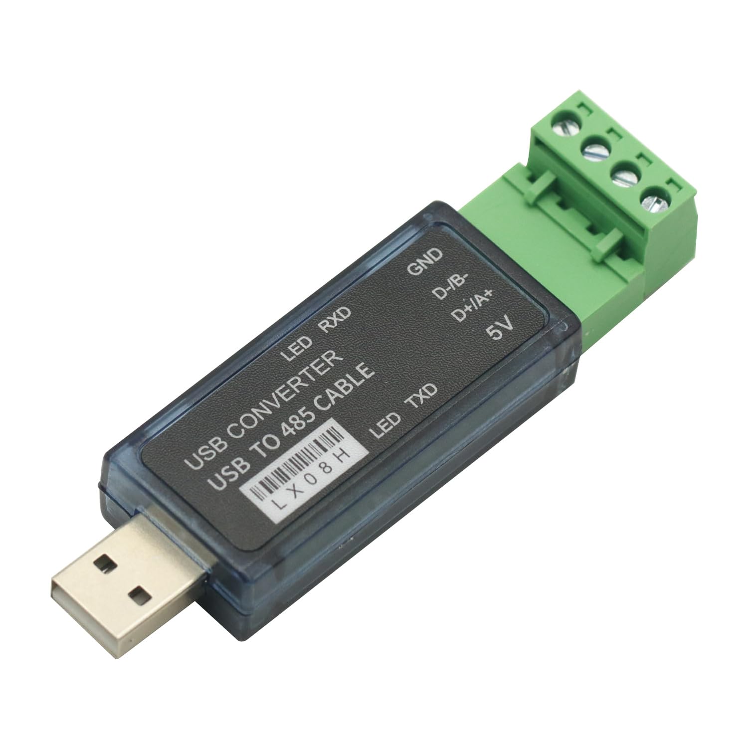
Figure 1: GODIYMODULES Industrial USB to RS485 Converter
2. Features
- Supports STC MCU download.
- Adjustable baud rate: 300 to 115200 BPS.
- Includes software for serial port setup and power supply configuration.
- Provides 5V, 200mA current to external devices.
- Signal indication: Red LED for data receiving (RXD).
- Signal indication: Green LED for data transmitting (TXD).

Figure 2: Converter with LED RXD, LED TXD, GND, D-/B-, D+/A+, and 5V labels
3. Specifications
| Attribute | Value |
|---|---|
| Model Number | db620c38-21a9-43cd-90fb-dbaa93129d07 |
| Brand | GODIYMODULES |
| Connector Type | USB to RS485 Terminal Block |
| Compatible Devices | Desktop PCs, PLCs, MCUs, and other RS485 devices |
| Number of Ports | 1 (USB) to 1 (RS485) |
| Baud Rate | 300-115200 BPS |
| Output Voltage/Current | 5V, 200mA (for external devices) |
| Color | Green (terminal block) |
| Item Weight | 1.06 ounces (approx. 30 grams) |
| Package Dimensions | 3.94 x 1.98 x 0.79 inches (approx. 10 x 5 x 2 cm) |
4. Setup and Installation
Follow these steps to set up your Industrial USB to RS485 Converter:
- Driver Installation: Before connecting the converter, install the necessary USB serial port drivers on your computer. These drivers are typically provided on a mini-CD or available for download from the manufacturer's website.
- Connect to Computer: Plug the USB end of the converter into an available USB port on your computer. The operating system should detect the new hardware and assign a COM port number.
- Identify COM Port: Verify the assigned COM port number through your computer's Device Manager (e.g., "Ports (COM & LPT)").
- Wiring the RS485 Side: Connect your RS485 device to the terminal block of the converter. Ensure correct polarity for D+/A+ and D-/B-. Refer to the connection diagrams below for common configurations.
4.1 Connection Diagrams

Figure 3: Point-to-Point / 2-line Half-Duplex Connection (PC1 to single RS485 device)
- Connect the converter's D+/A+ terminal to the RS485 device's 485+ terminal.
- Connect the converter's D-/B- terminal to the RS485 device's 485- terminal.
- The GND and 5V terminals are optional for power supply to external devices if needed.

Figure 4: Point-to-Multipoint / 2-line Half-Duplex Connection (PC1 to multiple RS485 devices)
- Connect the converter's D+/A+ terminal to the 485+ bus line.
- Connect the converter's D-/B- terminal to the 485- bus line.
- All RS485 devices should be connected in parallel to the same 485+ and 485- bus lines.
- Ensure proper termination resistors are used on the bus if required by your RS485 network.

Figure 5: LX08H to LX08H Half-Duplex Communication
- Connect D+/A+ of the first converter (PC1) to D+/A+ of the second converter (PC2).
- Connect D-/B- of the first converter (PC1) to D-/B- of the second converter (PC2).
- This configuration allows two computers to communicate via RS485 using two converters.
5. Operation
Once the converter is physically connected and drivers are installed, you can begin serial communication.
- Software Configuration: Use a serial communication program (e.g., PuTTY, RealTerm, or custom software) to configure the COM port settings. Ensure the baud rate, data bits, parity, and stop bits match those of your RS485 device.
- Data Transmission: Send and receive data through the configured COM port. The converter will automatically handle the conversion between USB and RS485 signals.
- LED Indicators:
- The Red LED (RXD) will flash when the converter is receiving data from the RS485 bus.
- The Green LED (TXD) will flash when the converter is transmitting data to the RS485 bus.
- External Power Supply: If your external RS485 device requires power, you can utilize the 5V and GND terminals on the converter, which provide up to 200mA. Ensure your device's power requirements do not exceed this limit.
6. Maintenance
The GODIYMODULES Industrial USB to RS485 Converter is designed for durability and requires minimal maintenance.
- Cleaning: Keep the device clean and free from dust. Use a soft, dry cloth for cleaning. Avoid liquid cleaners.
- Storage: Store the converter in a cool, dry place away from direct sunlight and extreme temperatures when not in use.
- Handling: Handle the device with care to prevent physical damage to the USB connector or terminal block.
7. Troubleshooting
| Problem | Possible Cause | Solution |
|---|---|---|
| Device not recognized by computer. | Missing or incorrect drivers. Faulty USB port. | Install the correct drivers. Try a different USB port. Check Device Manager for errors. |
| No data transmission/reception. | Incorrect wiring. Incorrect COM port settings (baud rate, parity, etc.). RS485 device not powered or faulty. | Verify RS485 wiring (D+/A+, D-/B-). Check COM port settings in your software. Ensure the RS485 device is operational. Check LED indicators for activity. |
| Intermittent communication. | Loose connections. Electrical noise/interference. Improper termination resistors on RS485 bus. | Secure all connections. Use shielded cables if necessary. Ensure proper RS485 bus termination. |
| Red/Green LEDs not flashing. | No data activity. Device not powered. | Ensure data is being sent/received. Check USB connection. |
8. Warranty and Support
For warranty information and technical support, please refer to the documentation provided with your purchase or contact GODIYMODULES customer service through their official website.


