
1. Introduction
The Mulcort ANENG PN108 is a portable, professional digital clamp meter designed for accurate electrical measurements. It features a digital LCD display with backlight for easy reading in various conditions. This instrument offers a wide range of functions including AC/DC voltage, AC/DC current, resistance, capacitance, frequency, temperature, diode test, continuity, and Non-Contact Voltage (NCV) detection. Its compact design, overload protection, and low battery indication make it an ideal tool for professionals, factories, schools, and home users.
Included in the package:
- 1 x ANENG PN108 Clamp Meter
- 1 x Temperature Probe
- 1 x Pair of Test Leads
- 1 x Storage Bag
- 1 x User Manual (English)

Figure 1.1: ANENG PN108 Digital Clamp Meter highlighting its core capabilities like AC/DC current, voltage, temperature, and resistance measurements.
2. Safety Information
To ensure safe operation and avoid damage to the meter, please read and follow all safety instructions carefully. Improper use can result in electric shock or damage to the instrument.
- Always adhere to local and national safety codes.
- Do not apply voltage or current that exceeds the maximum specified limits for the meter.
- Exercise extreme caution when working with live circuits. Voltages above 30V AC RMS, 42V peak, or 60V DC pose a shock hazard.
- Before measuring current, ensure the circuit is de-energized and the test leads are properly connected.
- Never use the meter if it appears damaged or if the insulation on the test leads is compromised.
- Ensure the battery cover is securely closed before operation.
- Do not operate the meter in explosive gas, vapor, or dusty environments.
- Remove test leads from the circuit before changing functions.
- Replace batteries immediately when the low battery indicator appears to ensure accurate readings.
3. Product Overview and Features
The ANENG PN108 clamp meter is designed for ease of use and reliability. Key components include the clamp jaw, function dial, LCD display, and control buttons.
3.1 Key Features
- 6000 Counts Display: Provides high-resolution measurements.
- AC/DC Current Measurement: Up to 600A using the clamp jaw.
- AC/DC Voltage Measurement: Up to 600V.
- Resistance, Capacitance, Frequency (Hz), Diode, Continuity: Comprehensive electrical testing capabilities.
- Temperature Measurement: With included temperature probe.
- NCV (Non-Contact Voltage) Detection: For identifying live wires without direct contact.
- LCD Backlight: Improves visibility in dimly lit environments.
- Flashlight: Built-in light for illuminating work areas.
- Data Hold: Freezes the current reading on the display.
- Auto Power Off: Conserves battery life by automatically shutting down after 15 minutes of inactivity.
- Low Battery Indication: Alerts when battery replacement is needed.

Figure 3.1: Overview of the ANENG PN108's measurement functions.
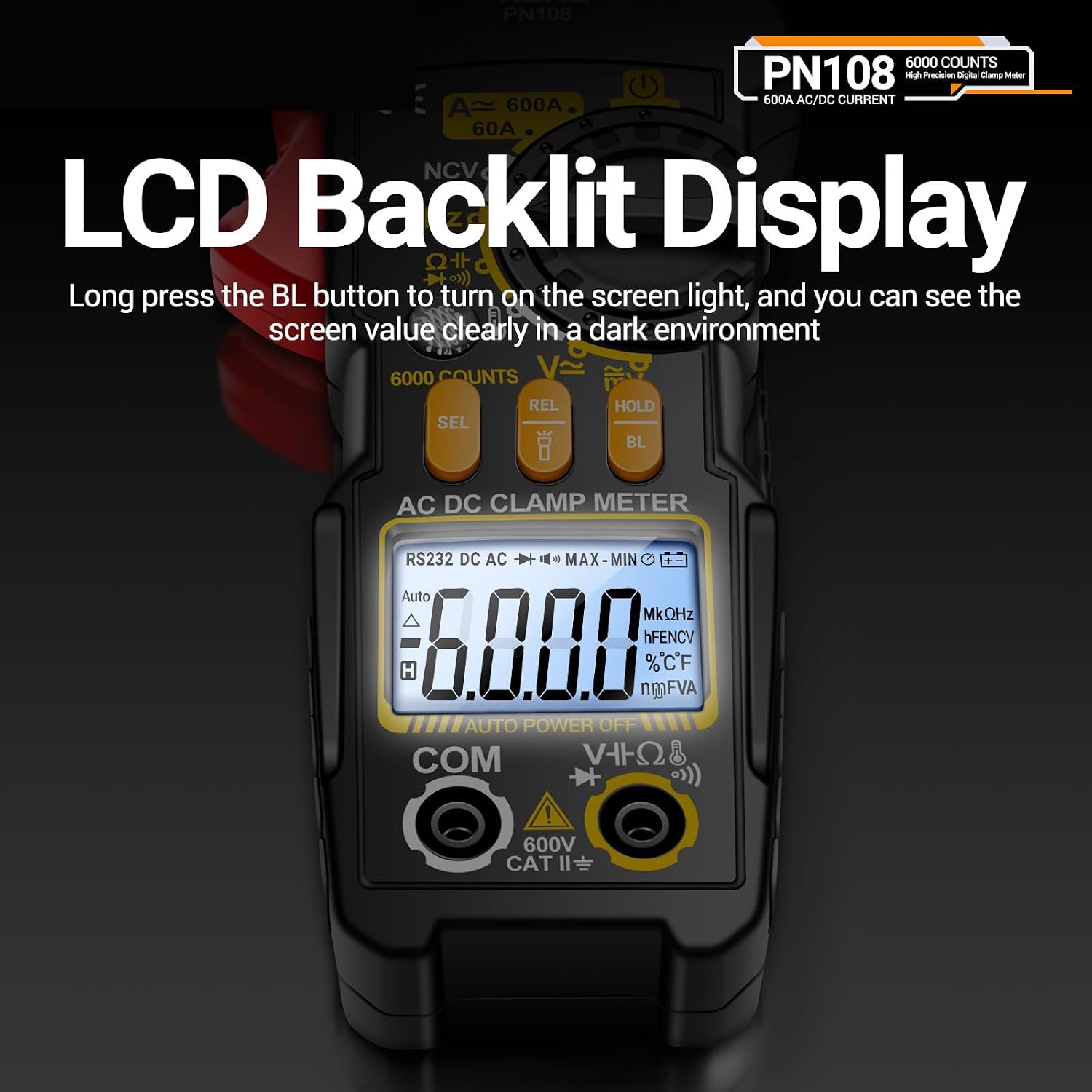
Figure 3.2: The LCD Backlit Display provides clear readings in dark environments. Press the 'BL' button to activate.

Figure 3.3: The built-in flashlight assists in illuminating dark work areas, enhancing safety and visibility.
4. Setup
4.1 Battery Installation
The ANENG PN108 requires two AAA batteries (not included) for operation.
- Ensure the meter is turned off.
- Locate the battery compartment on the back of the meter.
- Use a screwdriver to open the battery compartment cover.
- Insert two AAA batteries, observing the correct polarity (+ and -).
- Replace the battery compartment cover and secure it with the screw.
4.2 Connecting Test Leads
For voltage, resistance, capacitance, frequency, diode, continuity, and temperature measurements, connect the test leads as follows:
- Insert the red test lead into the 'VΩHz' input jack.
- Insert the black test lead into the 'COM' (common) input jack.
- For temperature measurements, connect the temperature probe to the 'VΩHz' and 'COM' jacks, ensuring correct polarity if applicable.
5. Operating Instructions
Turn the rotary dial to select the desired measurement function. Press the 'SEL' button to cycle through sub-functions if available within a dial position.
5.1 AC/DC Voltage Measurement
- Turn the rotary dial to the 'V' position. The meter will default to AC voltage. Press 'SEL' to switch to DC voltage if needed.
- Connect the red test lead to the positive side of the circuit and the black test lead to the negative side (or neutral/ground for AC).
- Read the voltage value on the LCD display.
5.2 AC/DC Current Measurement (Clamp)
The clamp jaw allows for non-contact current measurement.
- Turn the rotary dial to the 'A' position. The meter will default to AC current. Press 'SEL' to switch to DC current if needed.
- Open the clamp jaw and enclose only one conductor of the circuit. Ensure the conductor is centered within the jaw for accuracy.
- Read the current value on the LCD display.

Figure 5.1: Measuring AC current by clamping around a single conductor. The 2.6cm caliber clamp allows for various conductor sizes.

Figure 5.2: Measuring DC current, such as from a car battery, by clamping around a single wire without breaking the circuit.
5.3 Resistance Measurement
- Turn the rotary dial to the 'Ω' position.
- Ensure the circuit is de-energized before measuring resistance.
- Connect the test leads across the component to be measured.
- Read the resistance value on the LCD display.
5.4 Capacitance Measurement
- Turn the rotary dial to the 'Capacitance' position (often shared with Hz or Diode). Press 'SEL' if necessary.
- Ensure the capacitor is fully discharged before measurement.
- Connect the test leads across the capacitor terminals.
- Read the capacitance value on the LCD display.
5.5 Frequency (Hz) Measurement
- Turn the rotary dial to the 'Hz' position.
- Connect the test leads across the circuit or signal source.
- Read the frequency value on the LCD display.
5.6 Temperature Measurement
- Turn the rotary dial to the 'Temp' position (often indicated by a thermometer symbol).
- Connect the temperature probe to the meter's input jacks.
- Place the tip of the temperature probe on or in the object whose temperature is to be measured.
- Read the temperature value on the LCD display. Press 'SEL' to switch between Celsius and Fahrenheit.

Figure 5.3: Measuring temperature by connecting the temperature probe to the instrument and touching the object.
5.7 Diode Test and Continuity Test
- Turn the rotary dial to the 'Diode/Continuity' position (often indicated by diode and buzzer symbols). Press 'SEL' to switch between functions.
- Diode Test: Connect the red test lead to the anode and the black test lead to the cathode of the diode. The display will show the forward voltage drop. Reverse the leads to check for open circuit.
- Continuity Test: Connect the test leads across the circuit or component. If resistance is below approximately 50Ω, the buzzer will sound, indicating continuity.
5.8 NCV (Non-Contact Voltage) Detection
- Turn the rotary dial to the 'NCV' position.
- Move the top part of the meter (NCV sensor) close to the conductor or outlet.
- If AC voltage is detected, the indicator light will flash red, and an audible beep will sound, with the frequency of beeps increasing as the voltage strength increases.

Figure 5.4: NCV detection in progress. When AC voltage is detected, the meter flashes red and emits an alarm sound.
5.9 Data Hold Function
Press the 'HOLD' button to freeze the current reading on the display. Press it again to release the hold and resume live readings.
5.10 Backlight and Flashlight
- Backlight: Long press the 'BL' button to turn the LCD backlight on or off.
- Flashlight: Long press the flashlight button (often integrated with 'BL' or a separate button) to turn the flashlight on or off.
6. Maintenance
6.1 Cleaning
Wipe the meter with a damp cloth and mild detergent. Do not use abrasives or solvents. Keep the input terminals free of dirt and moisture.
6.2 Battery Replacement
When the low battery indicator appears on the display, replace the batteries as described in Section 4.1. Remove batteries if the meter is not used for an extended period.
6.3 Storage
Store the meter in a cool, dry place, away from direct sunlight and extreme temperatures. Use the provided storage bag to protect it from dust and physical damage.
7. Troubleshooting
| Problem | Possible Cause | Solution |
|---|---|---|
| No display or dim display | Dead or low batteries; Incorrect battery installation | Replace batteries; Check battery polarity |
| Incorrect readings | Wrong function selected; Poor test lead connection; Out of range; External interference | Select correct function; Ensure secure connections; Check measurement range; Move away from strong electromagnetic fields |
| No continuity beep | Circuit resistance too high; Buzzer function not selected | Ensure resistance is below 50Ω; Press 'SEL' to activate buzzer mode |
| Clamp meter not reading current | Only one conductor enclosed; Wrong current type (AC/DC) selected | Ensure only one conductor is in the clamp; Press 'SEL' to switch between AC and DC current |
8. Specifications
The following table outlines the technical specifications of the ANENG PN108 Digital Clamp Meter.

Figure 8.1: Detailed technical specifications for the ANENG PN108.
| Function | Range | Resolution | Precision |
|---|---|---|---|
| AC Voltage | 0mV-600V | 0.001V-0.1V | ±(1.2%+5) |
| DC Voltage | 0mV-600V | 0.001V-0.1V | ±(1.0%+5) |
| AC Current | 0A-600A | 0.001A-1.0A | ±(4.0%+20) |
| DC Current | 0A-600A | 0.01A-1A | ±(2.0%+8) |
| Resistance | 0Ω-20MΩ | 0.1Ω-0.1MΩ | ±(1.2%+3) |
| Capacitance | 0nF-99.99mF | 0.001nF-0.01mF | ±(5.0%+5) |
| Frequency (Hz) | 0Hz-99.99kHz | 0.001Hz-0.01kHz | ±(0.3%+5) |
| Temperature | 0℃-1000℃ / -60℉-1832℉ | 1℃ / 1℉ | ±(1.9%+5) / ±(1.9%+6) |
| NCV | Yes | N/A | N/A |
| Diode | Yes | N/A | N/A |
| Buzzer (Continuity) | Yes | N/A | N/A |
| Max Count | 6000 Counts | N/A | N/A |
| Auto Power Off | 15 minutes | N/A | N/A |
| Battery | 2 x AAA (not included) | N/A | N/A |
| Dimensions | 195 x 69.5 x 35 mm | N/A | N/A |
| Weight | 174 g | N/A | N/A |
| Material | ABS | N/A | N/A |
9. Warranty and Support
Specific warranty information for the Mulcort ANENG PN108 Digital Clamp Meter is not provided within this manual. For details regarding warranty coverage, terms, and conditions, please refer to the documentation included with your purchase or contact the seller or manufacturer directly.
For technical support, troubleshooting assistance beyond what is covered in this manual, or inquiries about replacement parts, please contact your point of purchase or the Mulcort customer service department.