1. Product Overview
The GLX-PCB-DSP PCB Display Board is a replacement part designed to enhance the functionality and reliability of your pool's salt chlorine generation system. It features a display screen for monitoring system operation and simplifies maintenance through easy connectivity.
This display board is compatible with specific Hayward Goldline Aqua-Rite and Aqua-Trol Salt Chlorine Generator models.

Image 1.1: Overview of the GLX-PCB-DSP PCB Display Board.
2. Compatibility
The GLX-PCB-DSP display board is specifically designed for compatibility with the following Hayward Goldline Salt Chlorine Generator models:
- Hayward Goldline Aqua-Rite Salt Chlorine Generators
- Hayward Goldline Aqua-Trol Salt Chlorine Generators
Specifically, it fits the following models:
- AQ-TROL-RJ
- AQ-TROL-RJ-TL
- AQ-TROL-HP
- AQ-TROL-HP-TL
This part replaces OEM part numbers: GLX-PCB-DSP, 220955, 2804-11, 2807-11, 624011, GLD-451-1009, GLXPCBDSP.

Image 2.1: The GLX-PCB-DSP board shown with a pool background, indicating its compatibility with Hayward Goldline Aqua-Rite and Aqua-Trol systems.
3. Features
- Integrated Display Screen: Provides real-time system parameters and error reminders, simplifying monitoring and troubleshooting.
- Enhanced Efficiency: Designed to improve the overall efficiency and reliability of your pool's chlorination system.
- Easy Connectivity: Simplifies the maintenance process with straightforward connection points.
- Power Compatibility: Connects to 120/240VAC power sources.
- Direct Mounting: Mounts directly into an AquaRite or AquaTrol power center.
- OEM Functionality: Offers all the functions of the original OEM mother board.

Image 3.1: The display board showing its screen and control knob, highlighting its user interface for system operation.
4. Installation Guide
The GLX-PCB-DSP display board is designed as a plug-and-play replacement, making installation straightforward. Ensure all power to the chlorinator system is disconnected before beginning installation.
4.1 Safety Precautions
- Always disconnect power to the salt chlorine generator at the circuit breaker before attempting any installation or maintenance.
- Wear appropriate personal protective equipment (PPE), such as safety glasses and gloves.
- If you are unsure about any step, consult a qualified electrician or pool technician.
4.2 Installation Steps
- Disconnect Power: Turn off the main power supply to your pool's salt chlorine generator at the breaker panel. Verify power is off using a voltage tester.
- Access Power Center: Open the enclosure of your AquaRite or AquaTrol power center to access the main circuit board (GLX-PCB-RITE).
- Remove Old Display Board: Carefully disconnect any cables or connectors attached to the existing display board. Note their positions for reinstallation. Gently unmount the old display board from the main circuit board.
- Install New Display Board: Align the GLX-PCB-DSP display board with the corresponding connectors and mounting points on the GLX-PCB-RITE main circuit board. Press firmly but gently to ensure it is securely seated.
- Reconnect Cables: Reconnect all previously disconnected cables and connectors to the new display board. Ensure all connections are snug.
- Close Enclosure: Securely close the power center enclosure.
- Restore Power: Turn the main power supply back on at the circuit breaker.

Image 4.1: The GLX-PCB-DSP board shown installed within a typical AquaRite or AquaTrol power center, demonstrating its integration.
5. Operation
Once installed and powered on, the GLX-PCB-DSP display board will show system operation parameters. The integrated display allows for easy monitoring of your salt chlorine generator's status.
5.1 Display Information
The display screen provides critical information about the chlorinator's performance, including but not limited to:
- Chlorine output percentage
- Salt level readings
- System status indicators (e.g., generating, standby, error)
- Error codes or reminders
5.2 Adjustments
The board may feature a rotary knob or buttons for navigating menus or adjusting settings, depending on the specific model of your Hayward Goldline system. Refer to your primary Hayward Goldline Aqua-Rite or Aqua-Trol manual for detailed instructions on adjusting settings via the display board.
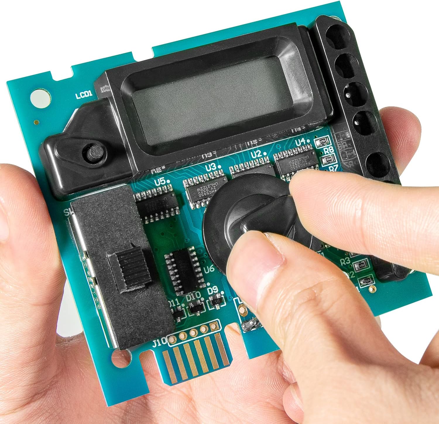
Image 5.1: A hand demonstrating the adjustment of the control knob on the display board, used for navigating settings.
6. Maintenance
The GLX-PCB-DSP display board itself requires minimal maintenance. However, ensuring the overall health of your salt chlorine generator system is crucial for its longevity and accurate performance.
- Keep Clean: Periodically inspect the display board and the interior of the power center for dust, debris, or moisture. Gently clean with a soft, dry cloth if necessary.
- Check Connections: During routine pool equipment checks, ensure all connections to the display board and main circuit board are secure and free from corrosion.
- System Health: For optimal performance, regularly maintain your salt chlorine generator cell and ensure proper water chemistry as per your Hayward Goldline system's recommendations.
7. Troubleshooting
This section addresses common issues related to the display board. For comprehensive troubleshooting of your entire salt chlorine generator system, refer to your primary Hayward Goldline Aqua-Rite or Aqua-Trol manual.
| Problem | Possible Cause | Solution |
|---|---|---|
| Display is blank or unlit. | No power to the unit; loose connection; faulty board. | Verify power supply to the chlorinator. Check all cable connections to the display board and main circuit board. If issues persist, the board may require replacement. |
| Incorrect readings on display. | Sensor issue; main board issue; display board malfunction. | Ensure proper water chemistry and sensor cleanliness. Consult your main chlorinator manual for sensor calibration or troubleshooting. If readings remain inaccurate, the display board or main board may be faulty. |
| Error code displayed. | System malfunction; specific component error. | Refer to your primary Hayward Goldline Aqua-Rite or Aqua-Trol manual for a list of error codes and their corresponding troubleshooting steps. |
8. Specifications
| Attribute | Detail |
|---|---|
| Model Number | HI-GLXPCB2 |
| Compatible OEM Part Numbers | GLX-PCB-DSP, 220955, 2804-11, 2807-11, 624011, GLD-451-1009, GLXPCBDSP |
| Product Dimensions | 6 x 5 x 1 inches |
| Item Weight | 8 ounces |
| Manufacturer | Hihitomorrow |
| Power Connection | 120/240VAC |

Image 8.1: A detailed top-down view of the GLX-PCB-DSP board, showing its components and layout.
9. Warranty and Support
Specific warranty information for the GLX-PCB-DSP display board is not provided in this manual. Please refer to the manufacturer's official website or contact their customer support for details regarding warranty coverage and terms.
For technical support or further assistance, please contact Hihitomorrow customer service or consult your original Hayward Goldline Aqua-Rite or Aqua-Trol system manual.


