
Introduction
This manual provides detailed instructions for the installation, operation, maintenance, and troubleshooting of your mGYDY 36V 48V 750W KT 25A Electric Bicycle Controller Kit. Please read this manual thoroughly before use to ensure proper function and safety.
Package Contents
The following items are included in your package:
- 1 x 25A Electric Motor Controller
- 1 x LCD5 Display
- 1 x TT009 Thumb Throttle
- 1 x 1T4 Cable
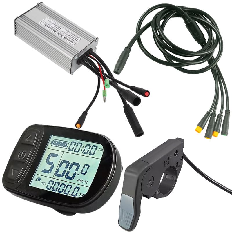
Figure 1: Overview of the mGYDY Electric Bicycle Controller Kit components.
Video 1: Unboxing and overview of the Electric Bike Brushless Controller Kit components.
Specifications
| Feature | Description |
|---|---|
| Item Type | Controller |
| Material | Aluminum Alloy, ABS |
| Controller Box Size | Approx. 125x66x39mm / 4.9x2.6x1.5in |
| Controller Type | Brushless Motor Controller |
| Connector Type | Waterproof Connector |
| Maximum Current | 25±1A |
| Rated Voltage | DC 36V / 48V |
| Speed Setting | 1-4.2V |
| Rated Current | 12A |
| Brake Input | Low Level |
| Low Voltage Protection | DC 30/40±0.5V |
| Applicable Motor | Usually 750W Motor |
| LCD5 Display Type | GD01 (or S866 as per video) |
| LCD5 Line Length | 225mm (WP Plug) |
| TT009 Throttle Type | Quick Thumb Throttle |
| TT009 Throttle Material | PC+ABS |
| TT009 Throttle Voltage | 12V 24V 36V 48V 52V 60V 72V |
| TT009 Throttle Installation | Right and Left |

Figure 2: Controller dimensions and basic specifications.

Figure 3: LCD5 Display dimensions and specifications.

Figure 4: TT009 Thumb Throttle specifications.
Setup and Installation
Proper installation is crucial for the safe and efficient operation of your e-bike kit. Ensure all connections are secure and waterproof where applicable.
Controller Wiring Instructions
Connect the corresponding line interfaces as described below to enable the kit's functions. It is essential to use this kit with a brushless motor and it is only compatible with KT series instrument products.
- Black Long Wire: Connect to the Motor Wire.
- Red and Black Single Big Wire: Connect as the Power Cord.
- Black Long Wire (Fine Hole): Connect to the One for Four/One for Five (9 Cores) cable.
- Black Line and Red Head: Connect to the Light Line.
- Black Wire and Yellow Head: Connect to the Power Assist Sensor Wire.

Figure 5: Controller wiring diagram showing various connections.

Figure 6: 1T4 Cable product connector details.
Display and Throttle Installation
The LCD5 display features an open design for easy installation on 22mm diameter handlebars, eliminating the need to remove the bike handlebars. The 1T4 cable connects the display, thumb throttle, and two brake levers to the controller.

Figure 7: LCD5 Display easy installation feature.
Video 2: Detailed demonstration of controller plug connections, including phase position, display, throttle, Hall sensor, battery, and e-brakes. Also shows display testing and parameter settings.
Operating Instructions
The LCD5 display provides various user parameter setting functions to customize your e-bike's performance.
LCD5 Display Functions
The display shows speed, PAS level, battery level, total mileage, single mileage, light indication, single trip time, and error codes. Refer to the diagram below for button functions and display indicators.

Figure 8: KT-LCD5 e-Bike Display User Manual - Functions and Display.
Parameter Settings
The display allows setting and adjusting motor parameters, speed measurement parameters, speed limit parameters, power parameters, power auxiliary control parameters, minimum controller voltage, and maximum current parameters. To enter parameter setting mode, press and hold the '+' and '-' buttons simultaneously. Use the '+' and '-' buttons to navigate and adjust values. Press the 'M' button to save and exit.
- P01: Backlight brightness (1-3 levels)
- P02: Change metric (0: Km, 1: Mile)
- P03: Battery voltage setting (24V/36V/48V/60V/72V, default 36V). Adjust 36V-60V voltage.
- P04: Hibernate mode time (1-60 minutes, 0: never enter this mode)
- P05: Total assist levels (0-5 levels)
- P06: Wheel size (inch)
- P07: Speed calculation (number of magnets for speed calculation, range: 1-255)
- P08: Speed limit range (0-100km/h)
- P09: Zero speed start (0: zero start, 1: non-zero start)
- P10: Driving mode selection
- P11: Assist sensitivity
- P12: Assist starting power
- P13: Assist disc type
- P14: Current limit of controller
- P15: Low voltage protection setting of controller
- P16: ODO distance reset
- P17: Cruise mode selection
- P18: Speed ratio
- P19: Assist level
- P20: Protocol selection
Maintenance
Regular maintenance ensures the longevity and optimal performance of your e-bike kit.
- Keep all components clean and free from dust and debris.
- Regularly check all electrical connections for tightness and signs of wear.
- Ensure waterproof connectors are properly sealed to prevent moisture ingress.
- Inspect cables for any damage or fraying and replace if necessary.
- Store the e-bike in a dry environment when not in use.
Troubleshooting
If you encounter issues, refer to the error codes displayed on the LCD5 and the following general troubleshooting tips.
Error Codes (from LCD5 Display)
| Code (Decimal) | Description |
|---|---|
| E00 | Normal |
| E01 | Reserved |
| E02 | Brake Error |
| E03 | Assist Sensor Error |
| E04 | 6KM/H Push Mode |
| E05 | Cruise Mode |
| E06 | Battery Low Voltage Protection |
| E07 | Motor Error |
| E08 | Throttle Error |
| E09 | Controller Error |
| E10 | COM Receive Error |
| E11 | COM Send Error |
| E12 | BMS Communication Error |
| E13 | Head Light Error |
For any error code, first check all connections. If the issue persists, consult a qualified technician.
Warranty and Support
Warranty Information
This product comes with a 1 Year Manufacturer Warranty. Please retain your proof of purchase for warranty claims. The warranty covers manufacturing defects under normal use conditions.
Customer Support
For technical assistance, troubleshooting, or warranty inquiries, please contact mGYDY customer support through your retailer or the official mGYDY website.