
1. Product Overview
The Febco LF860 Series 1" Lead-Free Bronze Reduced Pressure Zone Backflow Preventer Assembly with Flood Sensor is engineered to provide robust protection against cross-connection contamination. This device prevents the reverse flow of high-hazard fluids into potable water systems, safeguarding water quality from back-siphonage. Constructed from durable lead-free bronze, it ensures long-lasting performance and adherence to industry standards.
Key features include:
- Lead-Free Bronze construction for durability and compliance.
- Threaded quarter-turn ball valve shutoffs for reliable control.
- Top-mounted test cocks for easy testing and maintenance.
- Stainless steel spring-loaded check valves for effective backflow prevention.
- Pressure differential relief valve for system protection.
- Integrated flood sensor with SentryPlus Alert technology to detect excessive relief valve discharges.
- Modular relief valve and check valves for simplified in-line servicing.
This assembly is suitable for health hazard continuous pressure applications such as industrial plants, hospitals, morgues, chemical plants, irrigation systems, boiler feeds, and water lines where maximum protection is critical.

Figure 1: Febco LF860 Series 1" Lead-Free Bronze Reduced Pressure Zone Backflow Preventer Assembly.
2. Safety Information
Read all instructions carefully before installation, operation, or maintenance. Failure to follow these instructions may result in property damage, personal injury, or death. This device must be installed by a qualified professional in accordance with all local codes and regulations.
- Pressure Hazard: Ensure the water supply is shut off and the system is depressurized before attempting any installation or maintenance.
- Water Damage: Proper installation and regular maintenance are crucial to prevent leaks and potential water damage.
- Chemical Exposure: When handling the device, be aware of any residual chemicals in the system. Wear appropriate personal protective equipment (PPE).
- Heavy Object: The assembly can be heavy. Use proper lifting techniques or assistance to prevent injury.
- Electrical Hazard (Flood Sensor): If installing the optional flood sensor activation kit, ensure power is disconnected before making electrical connections.
3. Product Components
The Febco LF860 Series backflow preventer assembly includes the following main components:
- Lead-Free Bronze Body
- Inlet Shutoff Valve (Quarter-Turn Ball Valve)
- Outlet Shutoff Valve (Quarter-Turn Ball Valve)
- First Check Valve Assembly
- Second Check Valve Assembly
- Pressure Differential Relief Valve
- Test Cocks (Top-Mounted)
- Flood Sensor (Pre-installed on relief valve discharge)
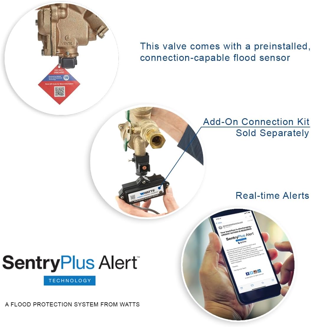
Figure 2: Side view of the backflow preventer, highlighting the quarter-turn shutoff valves and test cocks.
4. Installation
Installation must comply with all applicable federal, state, and local codes and standards. It is recommended that installation be performed by a licensed plumber or certified backflow prevention device tester.
- Site Selection: Choose a location that is accessible for maintenance and testing, protected from freezing, and allows for proper drainage of the relief valve discharge.
- Prepare Piping: Ensure the piping system is clean and free of debris. Flush the upstream piping thoroughly before connecting the assembly.
- Orient the Assembly: Install the backflow preventer in the correct flow direction as indicated by the arrow on the body. The assembly should be installed horizontally.
- Connect to Piping: Use appropriate threaded connections. Apply pipe sealant to male threads only. Do not overtighten connections.
- Support the Assembly: Provide adequate support for the assembly to prevent stress on the piping.
- Relief Valve Discharge: Connect the relief valve discharge to an air gap and drain line, ensuring it is visible and allows for proper drainage. The flood sensor is pre-installed on this discharge port.
- Initial Startup: Slowly open the upstream shutoff valve, then the downstream shutoff valve, allowing the system to fill gradually. Bleed air from the system through the test cocks.
- Testing: After installation, the assembly must be tested by a certified backflow prevention device tester to ensure proper operation.

Figure 3: Example of a backflow preventer installation. Ensure proper orientation and support.
5. Flood Sensor Setup and Activation
The Febco LF860 Series comes with a pre-installed flood sensor designed to detect excessive relief valve discharge. To activate the SentryPlus Alert technology and receive real-time notifications, an add-on connection kit is required (sold separately).
5.1. Flood Sensor Overview Video
Video 1: Flood Sensor Overview - Smart and Connected. This video demonstrates the flood sensor's function and the activation process using an add-on connection kit.
5.2. Activation Steps (with Add-On Connection Kit)
- Obtain Connection Kit: Purchase the appropriate add-on connection kit for your Febco LF860 Series backflow preventer from Watts.com or an authorized distributor.
- Install Activation Module: Follow the instructions provided with your add-on connection kit to install the flood sensor activation module. This typically involves connecting the module to the pre-installed flood sensor.
- Activate Sensor: Activate the sensor through the Syncta platform or integrate it with your existing Building Management System (BMS). Refer to the connection kit's specific instructions for detailed activation procedures.
- Receive Alerts: Once activated, the system will send real-time alerts to your designated contacts (e.g., via email or text) if excessive relief valve discharge is detected.


Figure 4: The pre-installed flood sensor (left) and the Watts SentryPlus Alert technology (right) for smart monitoring.
The flood sensor does not alter the mechanical operation of the backflow preventer and ensures continued compliance with all necessary codes and certifications.
6. Operation
Once properly installed and activated, the Febco LF860 Series backflow preventer operates automatically to protect your potable water supply. It continuously monitors pressure differentials and prevents backflow conditions (back-siphonage and back-pressure) by discharging water through the relief valve if a hazardous condition occurs.
- Normal Operation: Under normal conditions, water flows through the assembly without interruption.
- Backflow Event: If a backflow condition is detected, the check valves close, and the relief valve opens to discharge water, preventing contamination.
- Flood Sensor: The integrated flood sensor detects water discharge from the relief valve and, if activated with the connection kit, sends real-time alerts.
The quarter-turn shutoff valves are used to isolate the assembly for testing or maintenance. Always operate these valves slowly to prevent water hammer.
7. Maintenance
Regular maintenance is essential to ensure the continued proper functioning and longevity of your Febco LF860 Series backflow preventer. All maintenance should be performed by qualified personnel.
- Annual Testing: The backflow preventer must be tested annually by a certified backflow prevention device tester, or more frequently as required by local codes.
- Visual Inspection: Periodically inspect the assembly for any signs of leaks, corrosion, or damage. Ensure the relief valve discharge port is clear and unobstructed.
- Internal Component Servicing: The modular relief valve and check valves, along with other internal parts, are designed for in-line servicing from the top of the unit. This simplifies maintenance procedures. Refer to the detailed service manual for specific instructions on disassembling, cleaning, and reassembling internal components.
- Flood Sensor Check: If the flood sensor is activated, regularly check its connection and ensure it is free from debris. Confirm that alert notifications are being received as expected.
- Winterization: In climates where freezing temperatures occur, proper winterization procedures must be followed to prevent damage to the assembly. This typically involves draining the device.
8. Troubleshooting
This section provides general guidance for common issues. For complex problems, contact a certified professional or Febco technical support.
| Problem | Possible Cause | Solution |
|---|---|---|
| Constant Discharge from Relief Valve |
|
|
| No Flow Through Assembly |
|
|
| Flood Sensor Not Sending Alerts |
|
|
9. Specifications
| Attribute | Detail |
|---|---|
| Model Number | F683002 |
| Size | 1 Inch |
| Material | Lead-Free Bronze |
| Exterior Finish | Bronze |
| Inlet Connection Size | 1 Inches |
| Inlet Connection Type | Threaded |
| Outlet Connection Type | NPT |
| Number of Ports | 2 |
| Valve Type | Ball Valve (Shutoffs) |
| Thread Size | 1 inch |
| Thread Type | NPT |
| Item Dimensions (L x W x H) | 12.4 x 7.09 x 3.86 inches |
| Included Components | Valve (Assembly) |
| Certifications | ASME, NSF, RoHS, EPA, ULC, ASTM, ANSI, ISO 9001 |
| UPC | 643925581683 |
10. Warranty and Support
For specific warranty information regarding your Febco LF860 Series backflow preventer, please refer to the documentation included with your product or visit the official Febco website. Febco is committed to providing high-quality products and customer satisfaction.
For technical support, replacement parts, or further assistance, please contact Febco customer service or visit the Febco Store on Amazon or the official Watts website.