
Product Overview
The LiftMaster K1D8389-1CCMC is a UL325 Main Control Board Replacement Kit designed for various LiftMaster DC Pad-Mount Commercial and Residential UL325 Approved Gate Operators manufactured after 2016. This control board serves as a crucial component for the proper functioning of your gate operator system.
It is backwards compatible with older second-generation gate operators, provided that specific UL325 safety regulations are met, particularly regarding monitored entrapment protection systems.
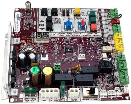
Figure 1: LiftMaster K1D8389-1CC Control Board. This image displays the main control board with various components, including fuses, capacitors, relays, and terminal blocks for connections. Key areas visible include the status display, test buttons, and adjustment potentiometers for timer and force settings.
Installation and Setup
Before beginning installation, ensure the gate operator's power supply is disconnected. Refer to the original gate operator's installation manual for specific wiring diagrams and safety precautions.
Compatibility and Safety Requirements:
- This control board is compatible with LiftMaster DC Pad-Mount Commercial and Residential UL325 Approved Gate Operators manufactured after 2016.
- For older second-generation gate operators, the following UL325 safety regulations are mandatory:
- UL325 Monitored Entrapment Protection System.
- Monitored Photoelectric Safety Eye Sensors or Edge Sensors on the OPEN Entrapment Zone are required.
- Important Note: Failure to implement the OPEN Monitored Entrapment Zone Protection System will prevent the unit from functioning correctly.
Installation Steps:
- Carefully remove the existing control board, noting all wire connections. It is recommended to take photographs for reference.
- Install the new K1D8389-1CCMC control board into the designated housing.
- Reconnect all wires to their corresponding terminals on the new board. Pay close attention to connections for DC Power, Motor, Battery, and safety devices.
- Ensure all UL325 safety devices (e.g., monitored photo eyes) are correctly installed and wired according to their respective manuals.
- Once all connections are secure, restore power to the gate operator.
- Proceed to the "Operating" section for initial setup and testing.
Operating Instructions
After installation, perform initial setup and testing to ensure proper operation and safety.
Initial Power-Up and Status Indicators:
- Upon power-up, observe the digital display (e.g., "88" or similar) and status LEDs on the board.
- Common status indicators include:
- INPUT POWER: Indicates main power supply is connected.
- BATT CHARGING: Indicates the battery is being charged.
- GATE MOVING: Illuminates when the gate is in motion.
- ENCODER: Indicates proper encoder function.
- ALARM: Signals a fault or error condition.
Adjustments and Test Buttons:
- LIMIT SETUP: Use the designated buttons or potentiometers to set the open and close limits of the gate. Refer to the gate operator's manual for precise limit setting procedures.
- TIMER TO CLOSE: Adjust the potentiometer (e.g., 5 to 60 seconds or 80 minutes) to set the automatic close delay.
- REVERSAL FORCE: Adjust the potentiometer to set the force sensitivity for obstruction detection. Test this setting carefully to ensure the gate reverses upon contact with an obstruction.
- TEST BUTTONS (OPEN, CLOSE, STOP): Use these buttons for manual operation and testing of the gate's movement and safety features.
Always test all safety features, including photo eyes and reversal mechanisms, after any adjustments or maintenance.
Maintenance
Regular maintenance ensures the longevity and reliable operation of your control board and gate system.
- Visual Inspection: Periodically inspect the control board for any signs of damage, loose connections, or corrosion. Ensure all terminal connections are secure.
- Cleaning: Keep the control board free from dust, dirt, and debris. Use a soft, dry brush or compressed air for cleaning. Do not use liquids or abrasive cleaners.
- Fuse Check: The board includes fuses (e.g., 30A 32V BATT FUSE, DC POWER FUSE). If the gate operator loses power or specific functions fail, check these fuses. Replace blown fuses only with fuses of the exact same type and rating.
- Battery Maintenance: If your system uses a backup battery, ensure it is properly connected and charging. Refer to the battery manufacturer's guidelines for specific maintenance.
Always disconnect power to the gate operator before performing any maintenance on the control board.
Troubleshooting
This section provides guidance for common issues. For complex problems, consult a qualified technician.
| Problem | Possible Cause | Solution |
|---|---|---|
| Gate does not move. | No power, blown fuse, safety device activated, motor issue. | Check power supply. Inspect fuses (BATT FUSE, DC POWER FUSE) and replace if blown. Verify safety devices (photo eyes) are clear and aligned. Check motor connections. |
| Gate reverses unexpectedly. | Obstruction detected, reversal force too sensitive, faulty safety device. | Clear any obstructions. Adjust REVERSAL FORCE potentiometer to a less sensitive setting. Inspect and test safety devices. |
| Gate does not close automatically. | TIMER TO CLOSE not set, safety device issue. | Adjust TIMER TO CLOSE potentiometer. Ensure no safety devices are detecting an obstruction preventing closure. |
| Status LED / Display shows error. | Specific fault condition. | Refer to the gate operator's full manual for specific error codes indicated by the status display or ALARM LED. |
Always ensure power is disconnected before inspecting or working on the control board or gate operator components.
Specifications
| Feature | Detail |
|---|---|
| Model Number | K1D8389-1CC-MC |
| Manufacturer | Liftmaster |
| Item Weight | 2 pounds |
| Product Dimensions | 6 x 6 x 1 inches |
| Included Components | Control Board |
| Compatibility | CSL24U, CSL24UL, CSW24U, CSW24UL, RSL12U, RSL12UL, RSW12U, RSW12UL (manufactured after 2016) |
| Safety Compliance | UL325 (requires Monitored Entrapment Protection System) |
Warranty and Support
For specific warranty information regarding the LiftMaster K1D8389-1CC Control Board, please refer to the documentation provided with your purchase or contact LiftMaster directly. Warranty terms typically cover manufacturing defects for a specified period.
For technical support, troubleshooting assistance beyond this manual, or to inquire about replacement parts, please contact LiftMaster customer service or an authorized LiftMaster dealer. Ensure you have your product model number (K1D8389-1CC-MC) and any relevant purchase details available when seeking support.
You can often find additional resources, FAQs, and contact information on the official LiftMaster website.


