1. Introduction
This manual provides detailed instructions for the installation, operation, and maintenance of your SASWELL Non-Programmable Thermostat 1H/1C, Model SAS900STK-0. This digital thermostat is designed for single-stage heating and cooling systems, offering precise temperature control and user-friendly features. Please read this manual thoroughly before installation and use to ensure proper function and safety.
2. Safety Information
- Always turn off power to the heating/cooling system at the main fuse or circuit breaker panel before installing or servicing the thermostat.
- Installation should be performed by a qualified technician if you are unsure about any steps.
- Ensure all wiring connections are secure to prevent short circuits or electrical hazards.
- Do not use this thermostat with voltages exceeding 30VAC.
- Keep the thermostat away from direct sunlight, drafts, and heat sources for accurate temperature readings.
3. Package Contents
Verify that your package contains the following items:
- SASWELL Non-Programmable Thermostat Unit
- Mounting Screws and Wall Anchors
- User Manual

Figure 3.1: Front view of the SASWELL Non-Programmable Thermostat 1H/1C.
4. Product Overview
The SASWELL Non-Programmable Thermostat features a clear LCD display and intuitive controls for managing your home's climate.
4.1 Key Features
- Wide Compatibility: Supports single-stage heating and cooling systems, heat pumps without auxiliary heating, hydronic heating, boilers, gas fireplaces (24V), and 750 millivolt systems.
- Easy DIY Installation: Designed for quick setup with dual power options (24VAC or AAA batteries). No C-wire required when battery-powered.
- Memory Retention: Preserves custom settings during power outages.
- Precise Temperature Control: Adjustable heating/cooling cycle rates, temperature calibration, and simultaneous heat/cool set point storage.
- User-Friendly Display: Easy-to-read digital screen with Fahrenheit or Celsius display options.
4.2 Thermostat Components and Display

Figure 4.1: Thermostat display and control elements.
The thermostat features a clear LCD screen and three control buttons on the right side, along with two slide switches at the bottom.
- (1) and (2) Up/Down Buttons: Used to raise or lower the setting temperature and select options in the configuration menu.
- (3) F Button: Used for filter alarm countdown and other functions.
- (4) FAN Switch (AUTO/ON): Controls the fan operation. In AUTO mode, the fan runs only when the heating/cooling system is active. In ON mode, the fan runs continuously.
- (5) SYSTEM Control Switch (COOL/OFF/HEAT): Selects the operating mode of the HVAC system.
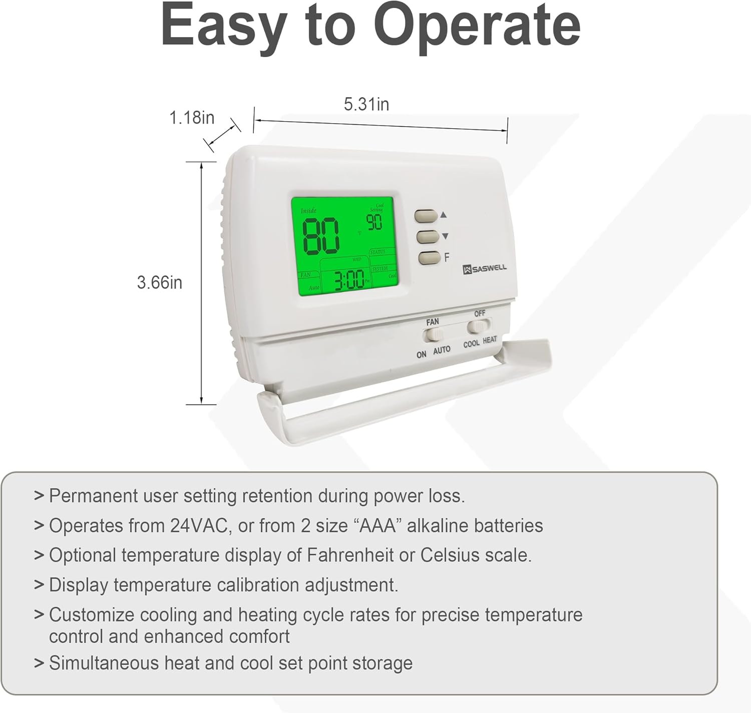
Figure 4.2: Thermostat dimensions and additional features.
- Permanent user setting retention during power loss.
- Operates from 24VAC, or from 2 size "AAA" alkaline batteries.
- Optional temperature display of Fahrenheit or Celsius scale.
- Display temperature calibration adjustment.
- Customize cooling and heating cycle rates for precise temperature control and enhanced comfort.
- Simultaneous heat and cool set point storage.
5. Installation
Before beginning installation, ensure the power to your HVAC system is turned off at the circuit breaker. This thermostat is designed for easy DIY installation, but professional assistance is recommended if you are unfamiliar with electrical wiring.
5.1 Wiring Diagrams
The thermostat supports various wiring configurations. Refer to the diagrams below to identify the correct wiring for your system. The thermostat can be powered by 24VAC or AAA batteries. If powered by batteries, a C-wire is not required.

Figure 5.1: Wiring schematics for common system types.
- Typical 1H/1C System (1 Transformer): Connect R to Rh (with jumper to Rc), W to W, Y to Y, G to G. C-wire is optional if using batteries.
- Cool Only System: Connect R to Rh (with jumper to Rc), Y to Y, G to G. C-wire is optional if using batteries.
- 1H/1C Heat Pump: Connect R to Rh (with jumper to Rc), W to W, Y to Y, G to G. If the system defaults to heating mode, connect the reversing valve signal wire to the B terminal. If the system defaults to cooling mode, connect the reversing valve signal wire to the O terminal. C-wire is optional if using batteries.

Figure 5.2: Wiring schematics for heating-only and volt-free systems.
- Heating Only System with Fan (Gas Fireplace 24V, Gas/Electric/Oil Furnace Forced-Air Heating): Connect R to Rh (with jumper to Rc), W to W, G to G. No C-wire required if the thermostat is powered by batteries.
- Heating Only without Fan (Hydronic Heating System): Remove the jumper wire between Rh and Rc. Connect R to Rh, W to W. No C-wire required if the thermostat is powered by batteries.
- Volt-Free System Heating Only (750 Millivolt/Boiler System): Remove the jumper wire between Rh and Rc. Connect R to Rh, W to W. The thermostat should be powered by batteries, and a C-wire is not needed.
5.2 Mounting the Thermostat
- Turn off power to your heating/cooling system at the circuit breaker.
- Remove your old thermostat from the wall.
- Label the wires connected to your old thermostat with the corresponding terminal letters.
- Mount the new thermostat's backplate to the wall using the provided screws and anchors.
- Connect the labeled wires to the appropriate terminals on the new thermostat's backplate according to the wiring diagrams in Section 5.1.
- If using battery power, insert 2 AAA alkaline batteries into the battery compartment.
- Attach the thermostat front panel to the backplate.
- Restore power to your heating/cooling system.

Figure 5.3: Illustration of thermostat installation.
6. Operation
This section describes the basic operation of your SASWELL Non-Programmable Thermostat.
6.1 Setting the System Mode
Use the SYSTEM slide switch at the bottom of the thermostat to select the desired operating mode:
- COOL: The thermostat will operate your cooling system.
- OFF: The heating and cooling systems are turned off.
- HEAT: The thermostat will operate your heating system.
6.2 Setting the Fan Mode
Use the FAN slide switch at the bottom of the thermostat to select the desired fan operation:
- AUTO: The fan runs only when the heating or cooling system is actively operating.
- ON: The fan runs continuously, regardless of whether the heating or cooling system is active.
6.3 Adjusting the Temperature
To adjust the desired temperature (set point):
- Ensure the system mode is set to HEAT or COOL.
- Press the ▲ (Up) or ▼ (Down) buttons to increase or decrease the set temperature.
- The display will show the current set point. The thermostat will then work to maintain this temperature.
7. Settings and Configuration
Your thermostat has several configurable settings to optimize its performance and display.
7.1 Temperature Display (Fahrenheit/Celsius)
The thermostat can display temperature in either Fahrenheit (℉) or Celsius (℃). Refer to the full user manual for specific instructions on how to switch between these modes, typically found within the advanced settings menu accessed by holding down certain buttons.
7.2 Temperature Calibration
If you believe the thermostat's temperature reading is inaccurate, it can be calibrated. Consult the detailed user manual for the procedure to access and adjust the temperature calibration setting.
7.3 Cycle Rate Adjustment
The heating and cooling cycle rates can be adjusted to fine-tune system performance and comfort. This advanced setting controls how frequently your system turns on and off. Refer to the comprehensive manual for instructions on modifying these settings.
8. Compatibility
The SASWELL Non-Programmable Thermostat is designed for wide compatibility with various HVAC systems. Please review the lists below to ensure your system is supported.

Figure 8.1: Visual representation of compatible and incompatible systems.
Compatible Systems:
- Conventional Single-Stage Heating & Cooling System
- Hydronic Heating System
- Cooling Only Systems
- 750 Millivolt Systems
- Boilers
- Gas Fireplaces (24V)
- Gas/Electric/Oil Furnace Forced-Air Heating
- Heat Pump without Auxiliary Heating (no electric or gas backup)
Incompatible Systems:
- Multistage Heating & Cooling
- Heat Pump with Emergency Heating
- Heat Pump with Auxiliary Heating
- Electric Baseboard Heat (120-240 Volts)
- Mini Split Systems
- Dual Fuel Hybrid Heating
- RV Thermostats
- Radiant Ceiling Heat
- Convectors
Note: Before purchase or installation, verify that your existing thermostat's wiring base supports 2 to 5 wires and matches the compatible system types listed above.
9. Troubleshooting
If you encounter issues with your thermostat, refer to the following common troubleshooting steps:
- No Display / Thermostat Not Responding:
- Check if the power to the HVAC system is on at the circuit breaker.
- If using battery power, replace the AAA batteries with fresh ones.
- Ensure all wiring connections are secure at the thermostat and the HVAC system.
- System Not Heating/Cooling:
- Verify the SYSTEM switch is set to HEAT or COOL.
- Check that the set temperature is above (for heating) or below (for cooling) the current room temperature.
- Ensure the fan switch is set to AUTO or ON.
- Confirm that the HVAC system itself is operational.
- Inaccurate Temperature Reading:
- Ensure the thermostat is not exposed to direct sunlight, drafts, or heat sources.
- Consider performing a temperature calibration as described in Section 7.2.
- Backlight Issues:
- If the backlight does not stay on as expected, ensure the C-wire is properly connected if you intend for continuous backlight operation. If running on batteries, the backlight duration is limited to conserve power.
For further assistance, please contact SASWELL customer support.
10. Specifications
| Feature | Specification |
|---|---|
| Brand | SASWELL |
| Model Name | SAS900STK-0 |
| Controller Type | Push Button |
| Special Feature | Low Battery Indicator |
| Color | White |
| Specific Uses | Air Conditioner, Boiler, Furnace, Heat Pump |
| Temperature Control Type | Manual |
| Included Components | Temperature Sensor |
| Power Source | Dual Power (24VAC or AAA Batteries) |
| Item Weight | 0.23 Kilograms (8.1 ounces) |
| Shape | Square |
| Display Type | LCD |
| Control Method | Touch (Buttons) |
| Style | Non-Programmable |
| Manufacturer | SASWELL |
| Package Dimensions | 6.06 x 4.33 x 1.73 inches |
| First Available Date | September 20, 2024 |
11. Warranty and Support
For warranty information and technical support, please contact SASWELL directly. Details can typically be found on the manufacturer's official website or through your purchase documentation.
Manufacturer: SASWELL
Website: Visit the SASWELL Store on Amazon (for general brand information)


