
1. Introduction
This manual provides detailed instructions for the safe and efficient operation of your Aoleaby KPS605D DC Power Supply. The KPS605D is a single-channel adjustable digital DC power supply, capable of delivering 0-60V and 0-5A. It features precise voltage and current control, making it suitable for various laboratory, educational, and industrial applications.
Key features include:
- 4 operating modes: Constant Voltage (CV), Constant Current (CC), Constant Resistance (CR), Constant Power (CP).
- Dynamic mode operation up to 10KHz.
- Dynamic test functions: continuous, pulse, and toggle modes.
- Comprehensive protection functions: Over Voltage Protection (OVP), Over Current Protection (OCP), Over Power Protection (OPP), and Over Temperature Protection (OTP).
- Additional functions: Battery test, automatic test, and CR-LED function.
2. Safety Instructions
Please read and understand all safety instructions before operating the device. Failure to follow these instructions may result in electric shock, fire, or damage to the product.
- Ensure the input voltage selector switch on the rear panel matches your local power supply (110V or 220V) before connecting the power cord.
- Do not operate the power supply in wet or damp conditions.
- Do not open the casing; there are no user-serviceable parts inside. Refer servicing to qualified personnel.
- Ensure proper ventilation. Do not block the ventilation openings on the rear and sides of the unit.
- Use only the provided power cord and appropriate output cables.
- Always turn off the power supply and disconnect it from the mains before making or changing output connections.
- Avoid short-circuiting the output terminals for extended periods.
3. Product Overview
Familiarize yourself with the components and controls of your KPS605D DC Power Supply.
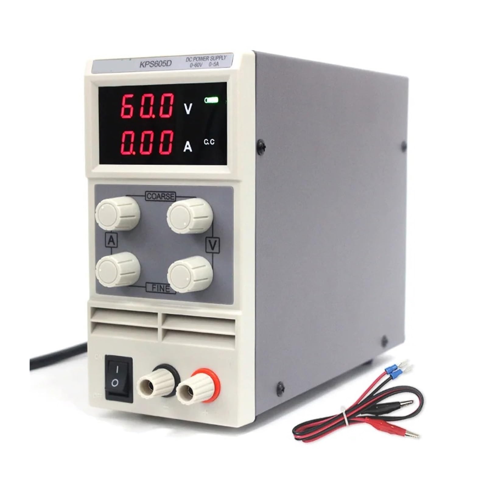
Figure 3.1: Front and side view of the Aoleaby KPS605D DC Power Supply, showing the digital display, voltage and current adjustment knobs, power switch, and output terminals. Insets highlight the coarse and fine adjustment knobs, the power switch and output terminals, the rear power input, and the cooling fan.
3.1 Front Panel Controls and Indicators
- Digital Display: Shows real-time output voltage (V) and current (A). Indicators for Constant Voltage (CV) and Constant Current (CC) modes are also present.
- Voltage Adjustment Knobs (COARSE/FINE): Used to set the desired output voltage. The COARSE knob makes large adjustments, while the FINE knob allows for precise tuning.
- Current Adjustment Knobs (COARSE/FINE): Used to set the desired current limit. The COARSE knob makes large adjustments, while the FINE knob allows for precise tuning.
- Power Switch (ON/OFF): Toggles the main power to the unit.
- Output Terminals (+/-): Red terminal for positive output, black terminal for negative output.
3.2 Rear Panel Components

Figure 3.2: Rear view of the Aoleaby KPS605D DC Power Supply. This image highlights the AC power input socket, the fuse holder, the cooling fan, and the crucial 115V/230V voltage selector switch. Insets show the selector switch set to 115V and 230V.
- AC Power Input Socket: Connects the power supply to the mains electricity using the provided power cord.
- Voltage Selector Switch (115V/230V): Allows selection of the appropriate input voltage for your region. Ensure this is set correctly before connecting to power.
- Cooling Fan: Provides necessary airflow to prevent overheating during operation.
- Fuse Holder: Contains the protective fuse for the unit.

Figure 3.3: Dimensions of the Aoleaby KPS605D DC Power Supply, showing a width of 8.4cm, height of 16.7cm, and depth of 21.1cm.
4. Setup
- Unpacking and Inspection: Carefully remove the power supply from its packaging. Inspect the unit for any signs of physical damage. If damage is found, do not operate the unit and contact your supplier.
- Voltage Selection: Locate the voltage selector switch on the rear panel (refer to Figure 3.2). Using a small screwdriver, set the switch to match your local AC mains voltage (110V or 220V). Incorrect voltage selection can cause severe damage to the unit.
- Power Connection: Ensure the power switch on the front panel is in the "OFF" position. Connect the provided AC power cord to the AC power input socket on the rear panel, then plug the other end into a grounded mains outlet.
- Placement: Place the power supply on a stable, level surface, ensuring adequate clearance around the cooling fan and ventilation openings for proper airflow.
5. Operating Instructions
5.1 Basic Operation (Constant Voltage/Constant Current)
- Power On: Flip the power switch on the front panel to the "ON" position. The digital display will illuminate, showing the current voltage and current settings.
- Pre-setting Voltage and Current (No Load):
- Ensure no load is connected to the output terminals.
- Adjust the Voltage COARSE and FINE knobs to set the desired output voltage.
- Adjust the Current COARSE and FINE knobs to set the desired current limit. The CC indicator will typically be off, and the CV indicator will be on.
- Connecting the Load: Connect your device or circuit to the output terminals, ensuring correct polarity (red to positive, black to negative).
- Operation with Load:
- If the load draws less current than the set limit, the power supply will operate in Constant Voltage (CV) mode, and the CV indicator will be lit. The output voltage will remain at the set value.
- If the load attempts to draw more current than the set limit, the power supply will automatically switch to Constant Current (CC) mode, and the CC indicator will be lit. The output current will be limited to the set value, and the output voltage will drop accordingly.
- Power Off: Disconnect the load, then flip the power switch to the "OFF" position.
5.2 Advanced Operating Modes
The KPS605D supports additional operating modes and functions for specialized applications:
- Constant Resistance (CR) Mode: Allows the power supply to act as a constant resistance load. Refer to the full technical manual for detailed setup and operation of this mode.
- Constant Power (CP) Mode: Allows the power supply to maintain a constant power output. Refer to the full technical manual for detailed setup and operation of this mode.
- Dynamic Mode (up to 10KHz): For applications requiring rapid changes in output.
- Dynamic Test Function: Includes continuous, pulse, and toggle modes for testing various load conditions.
- Battery Test Function: Specific function for testing battery characteristics.
- Automatic Test Function: For automated testing sequences.
- CR-LED Function: Specific function related to Constant Resistance mode for LED testing.
For detailed instructions on these advanced modes, please consult the comprehensive technical documentation provided with your unit or available from the manufacturer's website.
6. Maintenance
- Cleaning: Disconnect the power supply from the mains before cleaning. Use a soft, dry cloth to wipe the exterior. Do not use abrasive cleaners or solvents.
- Ventilation: Regularly check that the cooling fan and ventilation openings are free from dust and obstructions. Blocked vents can lead to overheating and damage.
- Storage: When not in use for extended periods, store the power supply in a cool, dry environment, away from direct sunlight and excessive humidity.
- Fuse Replacement: If the unit does not power on, check the fuse located in the fuse holder on the rear panel. Replace with a fuse of the same type and rating only. Refer to the specifications for fuse details.
7. Troubleshooting
If you encounter issues with your KPS605D power supply, refer to the following common problems and solutions:
| Problem | Possible Cause | Solution |
|---|---|---|
| Unit does not power on. | No AC power; Power cord loose; Blown fuse; Incorrect voltage selector setting. | Check AC power outlet; Ensure power cord is securely connected; Replace fuse (same type/rating); Verify voltage selector switch is set correctly (110V/220V). |
| No output voltage/current. | Output terminals not connected; Output voltage/current set to zero; Protection function activated (OVP, OCP, OPP, OTP). | Connect load to output terminals; Adjust voltage/current knobs; Check for short circuits or excessive load; Allow unit to cool if OTP is active. |
| Output voltage drops significantly under load. | Power supply operating in Constant Current (CC) mode; Load resistance too low. | Increase the current limit setting; Ensure the load's current requirement does not exceed the power supply's maximum output current. |
| Unit overheats. | Blocked ventilation; Excessive ambient temperature; Prolonged operation at maximum output. | Ensure ventilation openings are clear; Operate in a well-ventilated area; Reduce load or allow for cooling periods. |
If the problem persists after attempting these solutions, please contact customer support.
8. Specifications
| Parameter | Value |
|---|---|
| Input Voltage | AC110V/220V ±10% (selectable), 50/60Hz |
| Output Voltage Range | 0 - 60V |
| Output Current Range | 0 - 5A |
| Voltage Resolution | 100mV |
| Current Resolution | 10mA |
| Power Effect (CV) | ≤1% + 10mV |
| Load Effect (CV) | ≤1% + 10mV |
| Ripple and Noise (Vp-p) | ≤1% |
| Voltage Display Precision | ±1% + 1 digit |
| Current Display Precision | ±1% + 2 digits |
| Operating Environment | Temperature: -10°C to 45°C, Humidity: ≤85% RH |
| Dimensions (W×H×L) | 81mm × 165mm × 220mm (approx. 3.2in × 6.5in × 8.7in) |
| Item Weight | 2000 Grams (approx. 4.4 lbs) |
9. Warranty and Support
This Aoleaby KPS605D DC Power Supply is covered by a manufacturer's warranty. Please refer to the warranty card included with your product for specific terms and conditions. For technical support, troubleshooting assistance beyond this manual, or warranty claims, please contact your retailer or the Aoleaby customer service department.
Contact information can typically be found on the product packaging or the official Aoleaby website.