
1. Introduction
The Y&H MPPT 100A Solar Charge Controller features an advanced Maximum Power Point Tracking (MPPT) control algorithm. This technology rapidly tracks the maximum power point of the photovoltaic array in any environment, ensuring maximum energy harvest from the solar panel and significantly improving energy utilization in the solar system. It is suitable for various applications, including communication base stations, home power systems, traffic lights, solar street lamps, and courtyard lighting systems.
2. Key Features
- Advanced MPPT Technology: Automatically identifies 12V, 24V, 36V, or 48V systems with a tracking efficiency of no less than 99.5%.
- Multi-Battery Compatibility: Supports sealed, gel, flooded, and LiFePO4 battery types.
- LCD Display with Backlight: Provides real-time operational data including working mode, battery voltage, solar module charging current and voltage, battery discharge voltage and current, operating temperature, and delay time.
- Dual USB Charging Ports: Includes two 5V USB charging ports for convenience.
- 7 Operating Modes: Offers various modes to suit different application needs, including Load Mode, Light Control Mode, Light + Delayed Control Mode, Universal Control Mode, Manual Control Mode, Timing Control Mode, and Test Mode.
- Comprehensive Protections: Integrated protection against overheating, overcurrent, battery over-discharge, overvoltage, and overload.
- Enhanced Heat Dissipation: Features increased radiator fin spacing for improved natural heat dissipation, leading to lower controller temperature and enhanced charging efficiency.
3. Safety Information
Please read all instructions carefully before installation and operation. Failure to follow these instructions may result in damage to the controller, batteries, or other components, and may cause personal injury.
- Ensure all connections are correct and secure before applying power.
- Always connect the battery to the controller first, then the solar panel, and finally the load. Disconnect in the reverse order.
- Use appropriate cable sizes as recommended in the specifications section to prevent overheating and ensure efficient operation.
- Install the controller in a well-ventilated area, away from flammable materials and direct sunlight.
- Do not attempt to repair or modify the controller. Refer to qualified personnel for service.
- Wear appropriate personal protective equipment (PPE) when working with electrical systems.
Integrated Protections
The controller is equipped with the following safety features:
- Overheating Protection
- Overcurrent Protection
- Battery Over-discharge Protection
- Overvoltage Protection
- Overload Protection
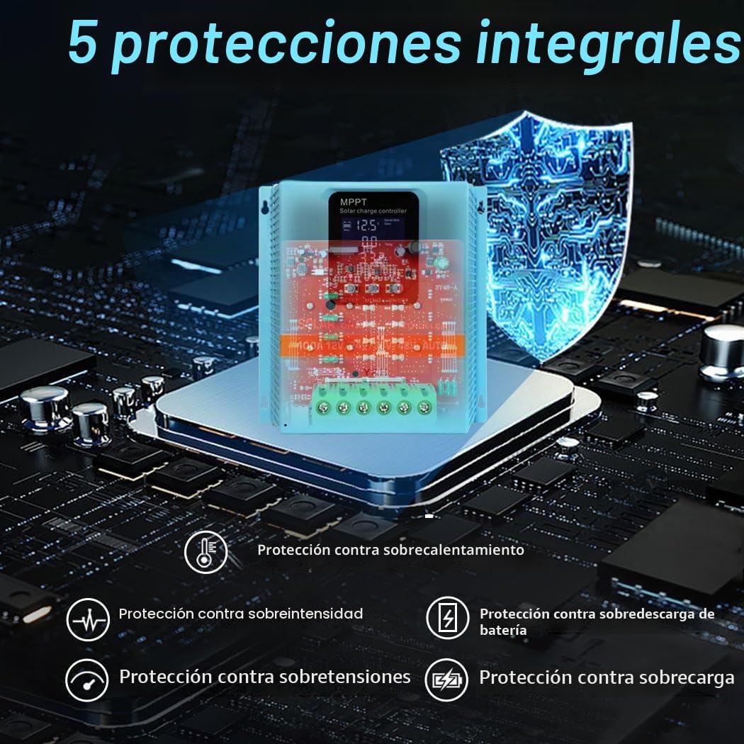
Figure 1: Illustration of the controller's five comprehensive protection features.
4. Product Overview and Components
The Y&H MPPT Solar Charge Controller is designed for ease of use and efficient performance. Below is an overview of its main components and ports.

Figure 2: Front and side view of the controller highlighting its ports and buttons.
Component Identification:
- LCD Display: Shows real-time system data and settings.
- Up Button: Used for navigation and increasing values.
- Down/On/Off Button: Used for navigation, decreasing values, and manually controlling the load.
- Dual USB Ports: Two 5V USB outputs for charging external devices.
- Solar Port: Connects to the solar panel array.
- Battery Port: Connects to the battery bank.
- Load Port: Connects to the DC load.
- DC Output Port: Additional DC output.
The large terminal ports facilitate easy cable access, and the integrated large heat sink ensures efficient heat dissipation, keeping the device cooler for optimal charging performance.
5. Setup and Installation
Proper installation is critical for the safe and efficient operation of your solar charge controller. Follow these steps carefully.
Wiring Instructions:
- Connect the Battery First: Connect the battery to the controller's battery terminals. Ensure correct polarity (positive to positive, negative to negative). The controller will automatically detect the system voltage (12V/24V/36V/48V).
- Connect the Solar Panel: Connect the solar panel array to the controller's solar terminals. Ensure correct polarity.
- Connect the DC Load: Connect the DC load to the controller's load terminals. Ensure correct polarity.
Important: Always connect the battery first and disconnect the battery last. Failure to follow this order may damage the controller.

Figure 3: Easy connection diagram for the solar charge controller.
Maximum Solar Input Power:
- 12V System: 1200W; Voc: 15-24V
- 24V System: 2400W; Voc: 30-48V
- 36V System: 3600W; Voc: 45-72V
- 48V System: 4800W; Voc: 60-100V
6. Operating Instructions
The controller's backlit LCD display provides comprehensive information about the system's status and allows for mode selection.
LCD Display Overview:

Figure 4: Detailed view of the LCD display and its information areas.
- Battery work status display area.
- Operating status area of the solar panel.
- Load output status and display areas for all parameters.
- Mode control display area.
- Normal and fault status display area.
The LCD dynamically displays operational data and working status, including solar panel voltage visualization, allowing for real-time understanding of PV input parameters.
Operating Modes:
The controller offers 7 distinct working modes:
- Load Mode: The load is never discharged.
- Light Control Mode: When the controller detects night, it will delay ten minutes and then begin discharging. When it detects daytime, it will delay ten minutes and then stop discharging.
- Light and Time Delay Control Mode: When the controller detects night, it will delay ten minutes, then begin discharging and start a countdown timer. If the timer reaches zero, discharging will stop. The maximum delay duration is 23:59.
- Universal Control Mode: Under normal conditions, discharging is always maintained.
- Manual Control Mode: Use the "▼" (down) button to manually enable or disable discharge.
- Timing Control Mode: Enables or disables discharge at regular, scheduled intervals.
- Test Mode: Similar to Light and Time Delay Control Mode, but without the ten-minute delay.
Low Voltage Protection Override: The controller will continue to discharge under low voltage protection if the "▼" button is held for 5 seconds. Discharge will only stop manually. Note that this action can potentially damage the battery; exercise extreme caution.
7. Maintenance
Regular maintenance ensures the longevity and optimal performance of your solar charge controller.
- Inspect Connections: Periodically check all wiring connections for tightness and corrosion. Loose connections can cause voltage drops and overheating.
- Clean the Controller: Keep the controller clean and free from dust and debris. Use a dry cloth to wipe the exterior. Ensure the heat sink fins are clear for proper airflow.
- Monitor Performance: Regularly check the LCD display for normal operation and any error codes. Monitor battery voltage and charging/discharging currents.
- Battery Health: Ensure your batteries are well-maintained according to their manufacturer's guidelines.
- Environmental Conditions: Ensure the installation environment remains within the recommended temperature and humidity ranges.
8. Troubleshooting
If you encounter issues with your solar charge controller, consider the following basic troubleshooting steps:
- No Display/No Power: Check battery connections and ensure the battery has sufficient charge. Verify all wiring is correct and secure.
- No Charging: Check solar panel connections and ensure the solar panels are receiving adequate sunlight. Verify solar panel voltage is within the controller's operating range.
- Load Not Working: Check load connections and ensure the load is not drawing excessive current (overload protection). Verify the selected operating mode allows for load discharge.
- Error Codes: Refer to the controller's display for any specific error codes. Consult the manufacturer's support for detailed explanations of error codes.
- Incorrect System Voltage: Ensure the battery voltage matches the auto-detected system voltage. If issues persist, disconnect all power, wait a few minutes, and reconnect the battery first.
For persistent issues or complex problems, please contact customer support.
9. Specifications
| Feature | Specification |
|---|---|
| Model Number | SA10048-UK |
| System Voltage | 12V/24V/36V/48V Auto |
| Max. Solar Input Voltage | 100V |
| Max. Solar Input Power (12V System) | 1200W |
| Max. Solar Input Power (24V System) | 2400W |
| Max. Solar Input Power (36V System) | 3600W |
| Max. Solar Input Power (48V System) | 4800W |
| Tracking Efficiency | ≥99.5% |
| Conversion Efficiency | Max. 99% |
| USB Output | Dual 5V Ports |
| Battery Compatibility | Sealed, Gel, Flooded, LiFePO4 |
| Dimensions (L x W x H) | 20.4 x 20 x 7.3 cm |
| Weight | 940 g |
| Material | Metal |
| Color | Royal Blue |
Recommended Cable Sizes:
It is crucial for system safety and efficient operation to use the appropriate cable for the PV module connection. To reduce the risk of injury and ensure optimal performance, use the recommended cable size indicated below:
| Model | Copper Cables | AWG | Air Circuit Breakers |
|---|---|---|---|
| SA10048 | 12mm² | 20AWG | 100A |

Figure 5: Controller dimensions and recommended cable specifications.
10. Warranty and Support
For warranty information, technical support, or service inquiries, please refer to the contact details provided with your purchase or visit the official Y&H website. Keep your purchase receipt as proof of purchase for warranty claims.


