
1. Introduction
The AYWHP LoRa V3 ESP32 Development Board is a versatile module integrating WiFi, Bluetooth, and LoRa communication capabilities. It features a dual-core 240MHz processor, a CP2102 USB-to-serial chip for easy programming, and a 0.96-inch OLED display for real-time information. Designed for various IoT applications, it supports Arduino development and the LoRaWAN protocol, enabling long-range, low-power communication.
2. Package Contents
Verify that all items listed below are included in your package. If any items are missing or damaged, please contact customer support.
- 1 x ESP32 V3 LoRa Module
- 1 x LoRa Antenna
- 1 x SH1.25X2P Male Cable (15cm)
- 1 x LoRa Protective Case
- 2 x Pin Headers

3. Product Overview
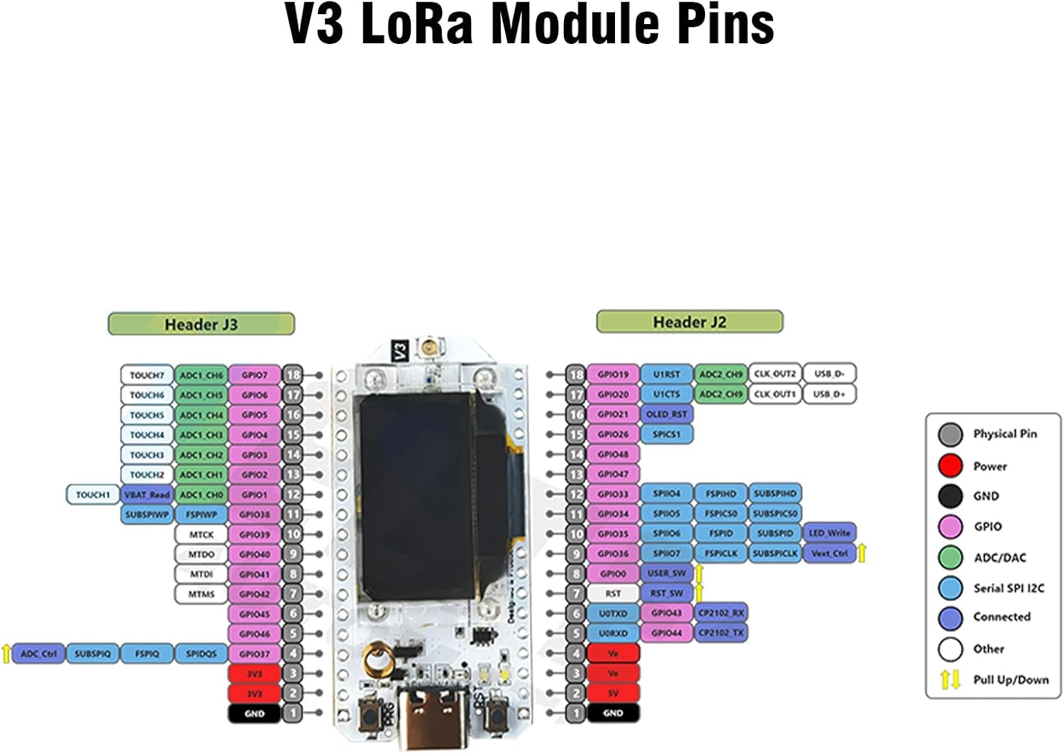
The AYWHP LoRa V3 ESP32 Development Board is designed for ease of use and integration into various projects. Below are key visual references and component details.



4. Specifications
Detailed technical specifications for the AYWHP LoRa V3 ESP32 Development Board:
| Feature | Detail |
|---|---|
| Processor | 240 MHz Dual-Core (Espressif) |
| RAM | LPDDR4 |
| Operating System | Arduino IDE |
| Connectivity Technology | Wi-Fi, LoRa, Bluetooth, USB |
| LoRaChip Support Frequency Band | SX1262 (868-915MHz) |
| OLED Display | 0.96 inch |
| USB to Serial Chip | CP2102 |
| Item Weight | 2.89 ounces |
| Package Dimensions | 5.63 x 4.21 x 0.98 inches |

5. Setup Instructions
Follow these steps to set up your AYWHP LoRa V3 ESP32 Development Board for programming and use.
5.1. Install Development Environment
- Download and Install Arduino IDE: Obtain the latest version of the Arduino Integrated Development Environment from the official Arduino website.
- Add ESP32 Board Support: In the Arduino IDE, go to
File > Preferences. In the "Additional Boards Manager URLs" field, add the URL for ESP32 board support. Then, go toTools > Board > Boards Manager, search for "ESP32", and install the package. - Install LoRa Library: Go to
Sketch > Include Library > Manage Libraries.... Search for "LoRa" (e.g., Arduino-LoRa) and install the necessary library.
5.2. Connect the Device
- Connect via USB: Use a USB cable to connect the development board to your computer.
- Select Board and Port: In the Arduino IDE, navigate to
Tools > Boardand select 'ESP32 Dev Module'. Then, go toTools > Portand select the correct serial port corresponding to your connected board.
5.3. Programming and Testing
- Select Example Code: Open an example sketch, such as 'LoRa Send' or 'LoRa Receive', from the LoRa library examples.
- Configure Frequency: Adjust the LoRa frequency in the code to 868MHz or 915MHz, depending on your regional specifications and antenna.
- Upload Code: Click the "Upload" button in the Arduino IDE to compile and upload the code to your board.
- Monitor Serial Port: Open the Serial Monitor (
Tools > Serial Monitor) to view debugging information and communication output.
Note: For Meshtastic firmware, visit the official Meshtastic website to download and flash the appropriate firmware for your Heltec V3 device. Ensure your device is plugged in via USB and follow the on-screen instructions for flashing.
6. Operating Instructions
6.1. OLED Display Usage
The integrated 0.96-inch OLED display can show debugging information, battery status, and other data. To control the display, use libraries such as U8g2 or Adafruit_SSD1306 in your Arduino code.
6.2. External Sensor Connection
The board provides various interfaces for connecting external sensors, including I2C, UART, and GPIO. Refer to the pinout diagram in Section 3 to identify the appropriate pins for your project requirements.
6.3. Meshtastic Communication
When flashed with Meshtastic firmware, the board can form a mesh network for long-range, low-power communication. Connect to the board via Bluetooth using the Meshtastic mobile application to send text messages, transmit GPS data, and share sensor information within the mesh network.
7. Applications
The AYWHP LoRa V3 ESP32 Development Board is suitable for a wide range of applications due to its robust RF circuit design and low-power capabilities:
- Smart Cities
- Smart Farms
- Home Automation
- Industrial Control
- Home Security Systems
- Wireless Metering
- General IoT Development
- Environmental Monitoring
- Robot Control
- Drone Control
- DIY Electronic Programs

8. Maintenance
To ensure the longevity and optimal performance of your development board, follow these maintenance guidelines:
- Keep Clean and Dry: Protect the board from dust, dirt, and moisture. Use a soft, dry cloth for cleaning.
- Avoid Extreme Conditions: Do not expose the board to extreme temperatures, high humidity, or corrosive environments.
- Handle with Care: Avoid dropping or subjecting the board to physical shocks, which can damage internal components.
9. Troubleshooting
If you encounter issues with your AYWHP LoRa V3 ESP32 Development Board, refer to the following common troubleshooting steps:
9.1. Connectivity Issues
- Check USB Cable: Ensure the USB cable is functional and securely connected to both the board and your computer.
- Verify Drivers: Confirm that the necessary CP2102 USB-to-serial drivers are installed on your computer.
- Correct Port Selection: In the Arduino IDE, ensure the correct serial port is selected under
Tools > Port.
9.2. Firmware Flashing Issues
- Boot Mode: Ensure the device is in boot mode during flashing. This often involves holding down a specific button (e.g., BOOT or PRG) while plugging in the USB cable or during the upload process.
- Baud Rate: Check if the baud rate setting in your flashing tool or Arduino IDE is appropriate for reliable communication.
- Try Different USB Port/Cable: Sometimes, issues can be resolved by using a different USB port on your computer or a different USB cable.
9.3. OLED Display Not Working
- Library Installation: Verify that the U8g2 or Adafruit_SSD1306 library is correctly installed in your Arduino IDE.
- Code Initialization: Check your code for proper initialization of the OLED display, including I2C address and display type.
10. Warranty and Support
For detailed warranty information, technical support, or to report any issues, please refer to the manufacturer's official website or contact their customer service directly. Keep your purchase receipt as proof of purchase for warranty claims.