1. Introduction
This manual provides comprehensive instructions for the installation, operation, maintenance, and troubleshooting of your PowMr M25A-12V/24V 25A MPPT Solar Charge Controller. This device is designed to efficiently manage power flow from your solar panels to your 12V or 24V battery system, supporting various battery types including lead-acid and lithium batteries.

Figure 1: PowMr M25A-12V/24V 25A MPPT Solar Charge Controller. This image shows the front view of the solar charge controller with its LCD screen and four control buttons.
2. Safety Instructions
- Read all instructions carefully before installation and operation.
- Ensure all power sources are disconnected before wiring to prevent electric shock.
- Use appropriate tools and wear protective gear during installation.
- Install the controller in a well-ventilated, dry environment, away from flammable materials.
- Ensure correct polarity when connecting batteries and solar panels. Incorrect wiring can damage the controller and other components.
- Do not disassemble or attempt to repair the controller yourself. Contact qualified personnel for service.
- The controller is designed for 12V/24V battery systems. Do not connect to other voltage systems.

Figure 2: Intelligent Protection Features. This image illustrates the nine built-in electronic protections of the PowMr solar controller, including over-discharging, overcharging, overload, short circuit, reverse current, temperature compensation, and reverse polarity protection.
3. Setup and Installation
Follow these steps for proper installation of your solar charge controller. Adhering to the correct connection sequence is crucial for system safety and functionality.
3.1. Preparation
- Solar Panel: Ensure your solar panel's voltage and power output are compatible with the controller and battery system.
- Battery: Use a compatible battery type (e.g., AGM, Gel, Flooded, Lithium) for your 12V or 24V system.
- Cables: Use appropriately sized cables to minimize power loss and prevent overheating. Ensure proper fusing for all connections.
3.2. Wiring Sequence
The correct wiring order is essential. Always connect the battery first, then the solar panels, and finally the load (if applicable).
- Connect the Battery to the Controller:
First, connect the positive (+) terminal of the battery to the battery positive (+) terminal on the charge controller. Then, connect the negative (-) terminal of the battery to the battery negative (-) terminal on the charge controller. Ensure correct polarity. The controller's display should illuminate, indicating a successful battery connection.
- Connect the Solar Panels to the Controller:
Connect the positive (+) lead from your solar panel array to the PV positive (+) terminal on the charge controller. Then, connect the negative (-) lead from your solar panel array to the PV negative (-) terminal on the charge controller. Ensure the solar panels are receiving sufficient sunlight for power generation.
- Connect the DC Load (Optional):
If you are using the DC load output, connect the positive (+) lead of your DC load to the load positive (+) terminal on the charge controller, and the negative (-) lead to the load negative (-) terminal. Refer to the operating section for load control settings.
Disconnection Sequence: To disconnect the system, reverse the order: first disconnect the load, then the solar panels, and finally the battery.

Figure 3: Basic Wiring Diagram. This diagram illustrates the connection of the solar charge controller to solar panels and a battery bank, showing the flow of power.

Figure 4: Simplified 2-Step Connection. This image provides a simplified visual guide for connecting the battery first, then the solar panels, and finally showing the charging process.
4. Operation
The PowMr M25A-12V/24V controller features an intuitive LCD screen and four buttons for easy monitoring and configuration.
4.1. LCD Display and Buttons
The backlit LCD screen displays real-time system status, including PV input, battery voltage, charging current, and load status. The four buttons (PV, BAT/▲, DC/▼, SET/⚙) allow navigation and parameter adjustment.

Figure 5: Backlit LCD Screen. This image shows the controller's LCD display, indicating PV input, battery status, and load output, along with the control buttons.
4.2. Battery Type Settings
The controller supports various battery types. To set the battery type:
- Long press the BAT/▲ key to enter the setting program.
- Use the BAT/▲ and DC/▼ keys to toggle through the battery type options.
- Press the SET/⚙ key to save and confirm your selection.
Pre-set options include Sealed, Gel, Flooded, and Lithium (LFP). A "User customize" option is available for specific parameter adjustments.

Figure 6: Compatible Battery Types. This image displays the controller's compatibility with various battery types, including AGM, GEL, FLD (Flooded), LI (Lithium), and SLA (Sealed Lead-Acid).
4.3. Load Work Modes
The controller offers multiple load work modes to manage your DC output:
- 00H: Load Turn OFF (Load is always off).
- 24H: Load always Turn ON (Load is continuously on).
- 01H~23H: Time control (Set the duration for which the load remains ON).
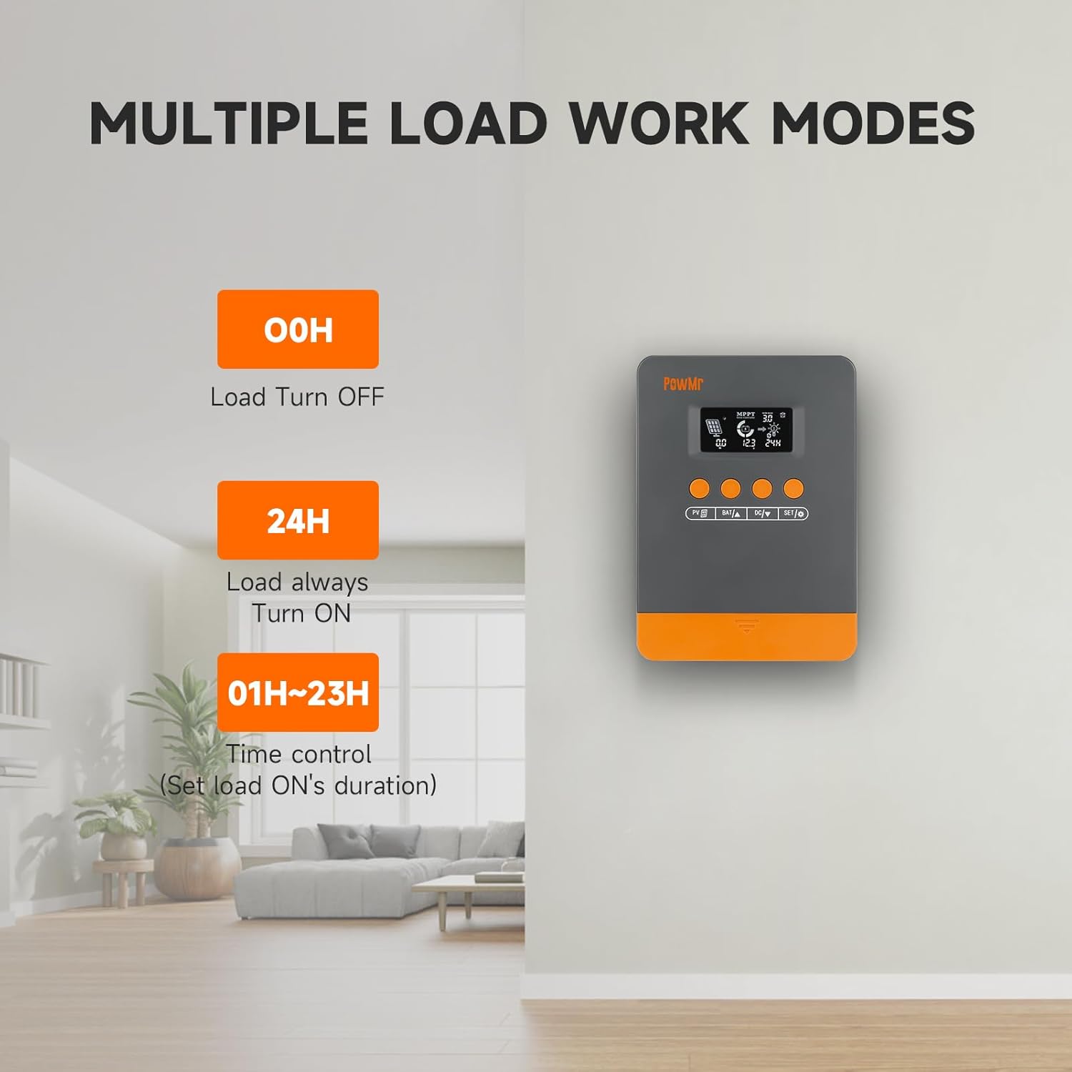
Figure 7: Load Work Modes. This image illustrates the different operational modes for the DC load output, including always off, always on, and time-controlled duration.
4.4. Calibrating Battery Voltage
If there is a discrepancy between the battery voltage monitored by the controller and a multimeter reading, you can calibrate the controller's voltage:
- Long press the BAT/▲ key to enter the setting program.
- Use the BAT/▲ and DC/▼ keys to adjust the value.
- Press the SET/⚙ key to save and confirm.

Figure 8: Battery Voltage Calibration. This image shows the controller's display during the battery voltage calibration process, allowing users to adjust the displayed voltage to match an external measurement.
5. Maintenance
Regular maintenance ensures optimal performance and longevity of your solar charge controller and system.
- Inspect Connections: Periodically check all wiring connections for tightness and corrosion. Loose connections can lead to power loss or damage.
- Clean Controller: Keep the controller clean and free from dust and debris. Use a dry cloth for cleaning. Ensure ventilation openings are not obstructed.
- Battery Inspection: Regularly inspect your batteries for signs of damage, leakage, or swelling. Ensure battery terminals are clean.
- Solar Panel Cleaning: Clean solar panels periodically to remove dirt, dust, or snow that may reduce efficiency.
- Monitor Performance: Observe the controller's display for any unusual readings or error codes.
6. Troubleshooting
This section provides guidance for common issues and their solutions. Refer to the LCD screen for specific error codes.
6.1. Error Codes and Solutions
| Fault Code | Cause | Solution |
|---|---|---|
| 18 | Input photovoltaic voltage too low | Increase the number of solar panels or connect them in series to raise the photovoltaic input voltage. |
| 60 | Overtemperature protection | Allow the equipment to cool to below the recovery temperature to resume normal charging and discharging. |
| 63 | Battery voltage too high | Measure to confirm if battery voltage exceeds rated voltage and disconnect photovoltaic array circuit breaker. |
| 65 | Battery voltage too low | Charge the battery until voltage exceeds the undervoltage recovery point. Refer to "3.7 Default/Parameters for Different Battery Types" for specific details. |
| 71 | Input photovoltaic voltage too high | Reduce the number of photovoltaic arrays connected to the controller to lower photovoltaic input, or adjust series and parallel connections to reduce voltage or current values. |
| 73 | Overcharging current | Reduce output terminal load to ensure total load is within rated limits of the controller and battery. |
| 72 | Overdischarging current | Reduce output terminal load to ensure total load is within rated limits of the controller and battery. |
6.2. General Troubleshooting Tips
- No Display/Power: Check battery connections and ensure the battery has sufficient charge. Verify polarity.
- Battery Not Charging:
- Ensure solar panels are connected correctly and receiving adequate sunlight.
- Check solar panel voltage and current.
- Verify battery type settings on the controller.
- Load Not Working:
- Check load connections and ensure the load is within the controller's rated capacity.
- Verify the load work mode setting (00H, 24H, or time control).
- Ensure the battery has sufficient charge.
- Inaccurate Readings: Calibrate battery voltage as described in Section 4.4.
7. Specifications
| Feature | Detail |
|---|---|
| Model | M25A-12V/24V (POW-M25-PRO) |
| Brand | PowMr |
| System Voltage | 12V / 24V Auto |
| Max. PV Input Power (12V System) | 300W |
| Max. PV Input Power (24V System) | 600W |
| Max. PV Open-Circuit Voltage | <60V |
| Rated Charge Current | 25A |
| Tracking Efficiency | Up to 98% |
| Peak Conversion Efficiency | Up to 97% |
| Supported Battery Types | Sealed, Gel, Flooded, Lithium (LFP), User-defined |
| Product Dimensions (L x W x H) | 4.52" x 2" x 7" (11.48 cm x 5.08 cm x 17.78 cm) |
| Item Weight | 1.1 Pounds (500 Grams) |
| Date First Available | September 3, 2024 |

Figure 9: System Wiring and Model Specifications. This image provides a detailed schematic for connecting solar panels, battery, and load, alongside a table outlining specifications for various PowMr MPPT controller models, including the M25A-12V/24V.
8. Warranty and Support
For warranty information and technical support, please refer to the official PowMr website or contact their customer service directly. Keep your purchase receipt for warranty claims.


