
1. Introduction
This manual provides essential information for the safe and effective use of your PPOZYLPC JD1914/JD1912 12V 40A 4-Pin Automotive Relay. This relay is designed to handle high current loads, allowing a low-current switch to control a high-current circuit, commonly found in automotive applications such as controlling headlights, fuel pumps, cooling fans, and other accessories.
Please read this manual thoroughly before installation and operation to ensure proper function and safety.
2. Safety Information
- Electrical Hazard: Always disconnect the vehicle's battery before installing or servicing any electrical components to prevent electrical shock or short circuits.
- Correct Voltage: Ensure the relay's voltage rating (12V) matches your vehicle's electrical system. Using an incorrect voltage can damage the relay or other components.
- Current Rating: Do not exceed the relay's maximum current rating (40A). Overloading the relay can cause overheating, failure, and potential fire hazards.
- Proper Wiring: Use appropriate gauge wires for the current load. Incorrect wire gauge can lead to overheating and fire.
- Secure Connections: Ensure all electrical connections are tight and properly insulated to prevent shorts and intermittent operation.
- Professional Installation: If you are unsure about any aspect of the installation, consult a qualified automotive electrician.
3. Product Components
The PPOZYLPC JD1914/JD1912 relay is a standard 4-pin automotive relay. It features a robust plastic housing and metal terminals for reliable electrical connections.
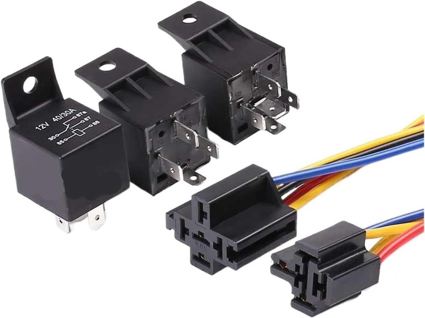
Image: Multiple PPOZYLPC JD1914/JD1912 4-pin automotive relays, some shown with optional wiring sockets. This image illustrates the general appearance of the relay and its potential connection points.
Relay Pin Configuration (4-Pin)
- Pin 30: Power Input (typically connected to the battery positive terminal via a fuse).
- Pin 85: Coil Ground (connected to a chassis ground or the negative terminal of the battery).
- Pin 86: Coil Power (connected to the switch that activates the relay, providing 12V when the switch is on).
- Pin 87: Normally Open (NO) Output (connected to the positive terminal of the device you want to power).
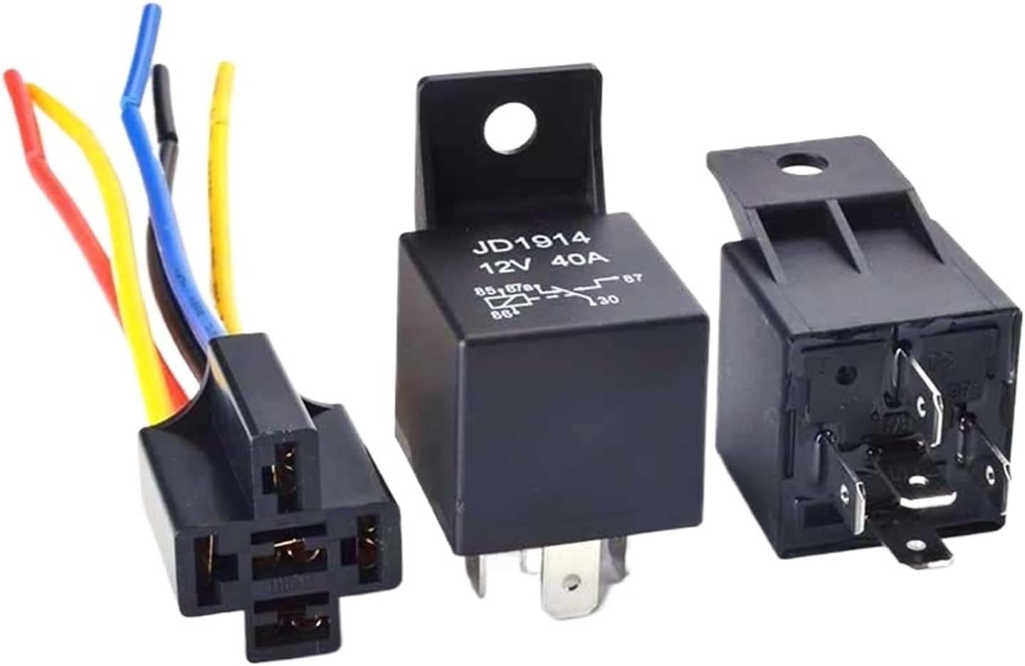
Image: A single PPOZYLPC JD1914/JD1912 4-pin automotive relay, clearly showing the pin numbers (30, 85, 86, 87) and a basic circuit diagram printed on its side, indicating its function.
4. Setup and Installation
This product is supplied as a 4-pin relay without a socket. Ensure you have the appropriate wiring and connectors for your application.
Wiring Steps:
- Disconnect Power: Before starting, disconnect the negative terminal of your vehicle's battery.
- Identify Pins: Locate the pin numbers (30, 85, 86, 87) on the relay. Refer to the 'Product Components' section for their functions.
- Connect Pin 30: Connect a fused 12V power source (e.g., directly from the battery or a main power distribution block) to Pin 30. The fuse should be rated appropriately for the circuit's maximum current draw.
- Connect Pin 85: Connect Pin 85 to a reliable chassis ground point or the negative terminal of the battery.
- Connect Pin 86: Connect Pin 86 to the positive output of your control switch (e.g., a toggle switch, ignition switch, or another relay's output). This pin receives 12V to energize the relay coil.
- Connect Pin 87: Connect Pin 87 to the positive input of the device you wish to power (e.g., a light bar, horn, or fan). The negative side of this device should be connected to ground.
- Secure Mounting: Mount the relay in a dry, secure location away from excessive heat, moisture, and vibration.
- Reconnect Power: Once all connections are secure and verified, reconnect the vehicle's battery.
5. Operating Instructions
The JD1914/JD1912 4-pin relay operates as a simple on/off switch for a high-current circuit, controlled by a low-current signal.
- When the control switch connected to Pin 86 is activated, 12V is supplied to the relay coil (between Pin 86 and Pin 85).
- This energizes the coil, creating an electromagnetic field that pulls the internal contact from Pin 30 to Pin 87.
- Current then flows from the power source (Pin 30) through the relay to the connected device (Pin 87), activating it.
- When the control switch is deactivated, power to the coil is cut, the electromagnetic field collapses, and the contact returns to its normally open position, breaking the circuit to the device.
6. Maintenance
Automotive relays are generally low-maintenance components. However, periodic checks can help ensure long-term reliability:
- Inspect Connections: Periodically check all wiring connections to the relay for tightness and corrosion. Loose or corroded connections can lead to resistance, heat buildup, and intermittent operation.
- Visual Inspection: Look for any signs of physical damage to the relay housing, such as cracks, melting, or discoloration, which could indicate overheating or internal failure.
- Functionality Test: If a circuit controlled by the relay malfunctions, test the relay by listening for an audible 'click' when the control switch is activated. A lack of click may indicate a faulty coil or control signal.
- Keep Clean: Ensure the relay and its connections are free from dirt, dust, and moisture.
7. Troubleshooting
If the device controlled by the relay is not functioning correctly, consider the following troubleshooting steps:
- Device Not Activating:
- No Click from Relay: Check for 12V at Pin 86 when the control switch is on, and a good ground at Pin 85. If either is missing, troubleshoot the control circuit.
- Relay Clicks, but Device Doesn't Work: Check for 12V at Pin 30 (main power input). If present, check for 12V at Pin 87 when the relay clicks. If 12V is at Pin 87, troubleshoot the wiring to the device or the device itself.
- Relay Overheating: Ensure the current draw of the connected device does not exceed 40A. Check for short circuits in the high-current circuit.
- Intermittent Operation: Inspect all connections for looseness or corrosion. Check for damaged wiring.
- Constant On/Off: This could indicate a faulty relay coil or a problem with the control signal.
Always replace a faulty relay with one of the same specifications (12V, 40A, 4-Pin).
8. Specifications
| Model Numbers | JD1914, JD1912 |
| Voltage Rating | 12V DC |
| Current Rating | 40A |
| Pin Configuration | 4-Pin (Normally Open - 1NO) |
| Package Dimensions | 1.18 x 0.79 x 0.39 inches (approximate) |
| Item Weight | 1.76 ounces (approximate) |
| Manufacturer | PPOZYLPC |
| Assembly Required | No |
9. Warranty and Support
Specific warranty information for this product is not provided in this manual. For details regarding warranty coverage, returns, or technical support, please refer to the product listing on the retailer's website or contact the seller directly. Keep your purchase receipt as proof of purchase.