
1. Introduction
This manual provides essential information for the installation, operation, and maintenance of the Cisco Catalyst 9300X-24Y-A Network Advantage Switch. The Cisco Catalyst 9300X Series is designed for high-density enterprise access and aggregation, offering advanced networking capabilities and high-speed connectivity.
The C9300X-24Y-A model features 24 ports capable of 25 Gigabit Ethernet (25G) SFP28 connectivity, making it suitable for demanding network environments requiring high bandwidth and performance.
2. Safety Information
Observe the following safety precautions to prevent injury and damage to the equipment:
- Electrical Safety: Ensure proper grounding. Do not operate the switch with damaged power cords. Disconnect power before servicing.
- Ventilation: Maintain adequate airflow around the switch. Do not block ventilation openings.
- Handling: The switch is heavy (approximately 23.1 pounds or 10.49 kg). Use proper lifting techniques or assistance to prevent injury.
- Environment: Operate the switch within specified temperature and humidity ranges. Avoid exposure to moisture or extreme temperatures.
3. Package Contents
Verify that your package contains the following items:
- Cisco Catalyst 9300X-24Y-A Switch
- Power cable
- Rack-mount kit (likely included for standard installation)
- Documentation (Quick Start Guide, Safety Information)
Note: Contents may vary slightly based on region or specific order. Contact your vendor if any items are missing or damaged.
4. Physical Description
4.1 Front Panel
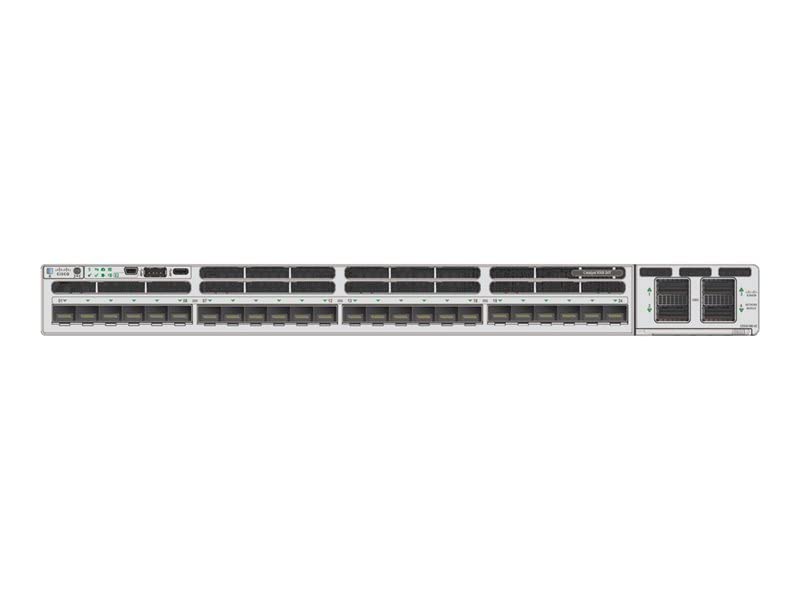
Figure 4.1: Front Panel of Cisco Catalyst 9300X-24Y-A Switch
The front panel of the Cisco Catalyst 9300X-24Y-A switch provides access to all network ports, console ports, and status indicators. Key components include:
- 24 x SFP28 Ports: These ports support 25 Gigabit Ethernet connectivity, compatible with SFP, SFP+, and SFP28 transceivers. They are numbered for easy identification.
- Uplink Module Slots: Located on the right side, these slots accommodate optional uplink modules for additional high-speed connectivity options.
- Console Port: Typically an RJ-45 or USB-C port for out-of-band management and initial configuration.
- USB Ports: USB Type-A and/or USB Type-C ports for external storage or console access.
- LED Indicators: Various LEDs (e.g., System, Status, Port Status) provide visual feedback on the switch's operational state and port activity.
4.2 Rear Panel
The rear panel typically houses power supply modules, fan modules, and grounding points. Specific configurations may vary.
5. Setup and Installation
5.1 Rack Mounting
- Attach the provided rack-mount brackets to the sides of the switch using the supplied screws.
- Secure the switch into a standard 19-inch equipment rack using appropriate rack screws. Ensure the switch is level and securely fastened.
5.2 Power Connection
- Connect the power cable to the power supply module(s) at the rear of the switch.
- Plug the other end of the power cable into a grounded AC power outlet (100 Volts nominal).
- Ensure the power supply LEDs illuminate, indicating proper power input.
5.3 Network Connections
- Insert compatible SFP28 transceivers into the desired 25G SFP28 ports on the front panel.
- Connect fiber optic or direct attach copper (DAC) cables from your network devices to the installed transceivers.
- Observe the port status LEDs to confirm link establishment.
5.4 Initial Configuration
For initial configuration, connect a console cable (RJ-45 to serial or USB-C to USB-A) from your management workstation to the console port on the switch. Use a terminal emulation program (e.g., PuTTY, Tera Term) with appropriate settings (typically 9600 baud, 8 data bits, no parity, 1 stop bit, no flow control) to access the command-line interface (CLI).
6. Operating the Switch
6.1 Power On
Once all connections are secure, power on the switch. The system will perform a power-on self-test (POST). During this process, various LEDs will flash. The System LED will typically turn solid green upon successful boot-up.
6.2 LED Indicators
- System LED: Indicates overall system status (e.g., green for normal operation, amber for warning, red for fault).
- Status LED: Provides additional system status information.
- Port Status LEDs: Located next to each SFP28 port, these LEDs indicate link status and activity (e.g., solid green for link, flashing green for activity, off for no link).
Refer to the Cisco documentation for a detailed explanation of all LED behaviors.
7. Maintenance
7.1 Environmental Considerations
Ensure the operating environment remains within the specified temperature and humidity ranges to ensure optimal performance and longevity of the switch. Avoid dusty environments.
7.2 Cleaning
Periodically clean the exterior of the switch with a soft, dry, lint-free cloth. Do not use liquid or aerosol cleaners directly on the device. Ensure ventilation openings are free from dust accumulation.
7.3 Firmware Updates
Regularly check the Cisco support website for the latest firmware updates. Applying updates can improve performance, add new features, and address security vulnerabilities. Follow Cisco's official procedures for firmware upgrades to prevent system disruption.
8. Troubleshooting
If you encounter issues with your Cisco Catalyst 9300X-24Y-A switch, consider the following basic troubleshooting steps:
- No Power: Verify the power cable is securely connected to both the switch and the power outlet. Check the power supply LEDs.
- No Link on Port: Ensure the SFP28 transceiver is correctly seated and the network cable is properly connected. Verify the connected device is powered on and configured correctly. Check the port status LED.
- System LED Indicates Fault: Consult the Cisco documentation for specific LED error codes or patterns. This usually indicates a hardware issue or critical system error.
- Cannot Access CLI: Verify console cable connection and terminal emulation settings. Ensure the switch has completed its boot sequence.
For more advanced troubleshooting, refer to the comprehensive documentation available on the official Cisco support website or contact Cisco Technical Assistance Center (TAC).
9. Specifications
| Feature | Detail |
|---|---|
| Brand | Cisco |
| Model | C9300X-24Y-A |
| Number of Ports | 24 |
| Interface Type | SFP28 (supports SFP, SFP+, 25G SFP28) |
| Data Transfer Rate | 25 Gigabits Per Second |
| Voltage | 100 Volts (AC) |
| Item Weight | 10.49 Kilograms (23.1 pounds) |
| Product Dimensions (L x W x H) | 22.05 x 21.65 x 8.66 inches |
| Case Material | Plastic (chassis is typically metal, but some components may be plastic) |
| Color | Gray |
| Compatible Devices | Desktop, Gaming Console, Laptop, Server (referring to devices that can connect to the network) |
| UPC | 703670607547 |
10. Warranty and Support
Cisco products typically come with a limited hardware warranty and access to Cisco's extensive support resources. For detailed warranty information, including terms and conditions, please refer to the warranty statement provided with your product or visit the official Cisco website.
For technical assistance, documentation, software downloads, and service requests, visit the Cisco Support Community or contact the Cisco Technical Assistance Center (TAC). Having your product serial number readily available will expedite support requests.
Cisco Support Website: www.cisco.com/go/support


