
1. Introduction
This manual provides detailed instructions for the safe and effective operation of your BSIDE Vector Network Analyzer. Please read this manual thoroughly before using the device and retain it for future reference. The BSIDE Vector Network Analyzer is a portable, high-performance instrument designed for measuring S-parameters, Voltage Standing Wave Ratio (VSWR), phase, delay, and displaying Smith Charts across a frequency range of 10KHz to 1.5GHz.
It is an essential tool for electronics engineers, amateur radio operators, and DIY enthusiasts involved in antenna analysis and RF circuit testing.

Figure 1.1: The BSIDE Vector Network Analyzer in use, highlighting its portable design, TFT color LCD, 3000mAh battery, and overall compact form factor for ham radio antenna analysis.
2. Package Contents
Upon unpacking, please verify that all items listed below are present and in good condition. If any items are missing or damaged, contact your vendor immediately.
- 1 x Antenna Analyzer Host
- 2 x SMA Male to Male RF Cable
- 1 x SMA Female to Female Connector
- 1 x SMA Simple Calibration Kit SHORT
- 1 x SMA Simple Calibration kit OPEN
- 1 x SMA Simple Calibration kit LOAD
- 1 x Charging Cable
- 1 x User Manual (this document)

Figure 2.1: All components included in the BSIDE Vector Network Analyzer package. This includes the main unit, two SMA male-to-male RF cables, an SMA female-to-female connector, a calibration kit (SHORT, OPEN, LOAD), a charging cable, and a protective carrying case.
3. Device Layout and Controls
Familiarize yourself with the physical components and controls of the Vector Network Analyzer.
- 3.98-inch Touch Screen: The primary interface for viewing measurements and interacting with the device.
- Function Wheel: A rotary encoder for menu navigation and parameter adjustment.
- Power Button: Located near the function wheel, used to turn the device on/off.
- PORT1 (S11): Input/output port for S11 measurements (reflection coefficient).
- PORT2 (S21): Input/output port for S21 measurements (transmission coefficient).
- USB-C Port: For charging and PC connectivity.

Figure 3.1: A detailed view of the 3.98-inch touch screen, which serves as the main interactive display for the Vector Network Analyzer. The touch interface allows for direct selection and adjustment of functions and parameters.

Figure 3.2: The full-viewing TFT LCD of the analyzer, showcasing its ability to display complex measurement data clearly from various angles. The image also indicates the RF output capability of the device.
4. Setup
4.1 Initial Charging
Before first use, fully charge the internal 3000mAh Li-ion battery. Connect the supplied charging cable to the USB-C port on the device and to a standard USB power adapter (not included). The charging indicator will show the charging status. A full charge typically takes several hours.

Figure 4.1: Visual representation emphasizing the 3000mAh rechargeable battery, which provides extended operational time for the device.
4.2 Powering On/Off
- To Power On: Press and hold the Power button (located near the function wheel) for approximately 2 seconds until the screen illuminates.
- To Power Off: Press and hold the Power button for approximately 3 seconds. A shutdown confirmation prompt may appear; confirm to power off.
4.3 Connecting Accessories
Use the provided SMA Male to Male RF cables to connect the analyzer to the device under test (DUT) or calibration standards. Ensure connections are finger-tight to avoid damage to the connectors and ensure good contact.
5. Operating Instructions
5.1 Basic Navigation
The device features a touch screen for direct interaction and a function wheel for precise adjustments. Tap on menu items or parameters to select them. Rotate the function wheel to change values or scroll through options. Press the function wheel to confirm selections.
5.2 Frequency Range Setting
To set the measurement frequency range:
- Tap on the "START" or "STOP" frequency display on the screen.
- Use the on-screen keypad or the function wheel to input the desired start and stop frequencies.
- Confirm the selection. The analyzer supports measurements from 10KHz to 1.5GHz.

Figure 5.1: The analyzer's screen indicating its broad frequency measurement capability, spanning from 10KHz up to 1.5GHz, suitable for HF, VHF, and UHF applications.
5.3 Calibration Process
Accurate measurements require proper calibration. The device supports up to 401 calibration points. Use the provided SHORT, OPEN, and LOAD calibration kits.
- From the main menu, navigate to the "Calibration" option.
- Select the desired calibration type (e.g., "Port 1 Calibration").
- Follow the on-screen prompts to connect the SHORT, OPEN, and LOAD standards to the specified port (e.g., PORT1) in sequence.
- Once all standards are measured, save the calibration data.
- Repeat for other ports or types of calibration as needed.
5.4 Measurement Modes
The analyzer can display various measurement parameters:
- S-Parameters (S11, S21): Reflection and transmission coefficients.
- VSWR (Voltage Standing Wave Ratio): Indicates impedance match.
- Phase: Phase response of the DUT.
- Delay: Group delay measurements.
- Smith Chart: Graphical representation of impedance.
To switch between modes, access the "Display" or "Measurement" menu and select the desired parameter. The device is capable of various antenna measurements including Short Wave, Balun, SSB, MF, HF, VHF, and UHF.
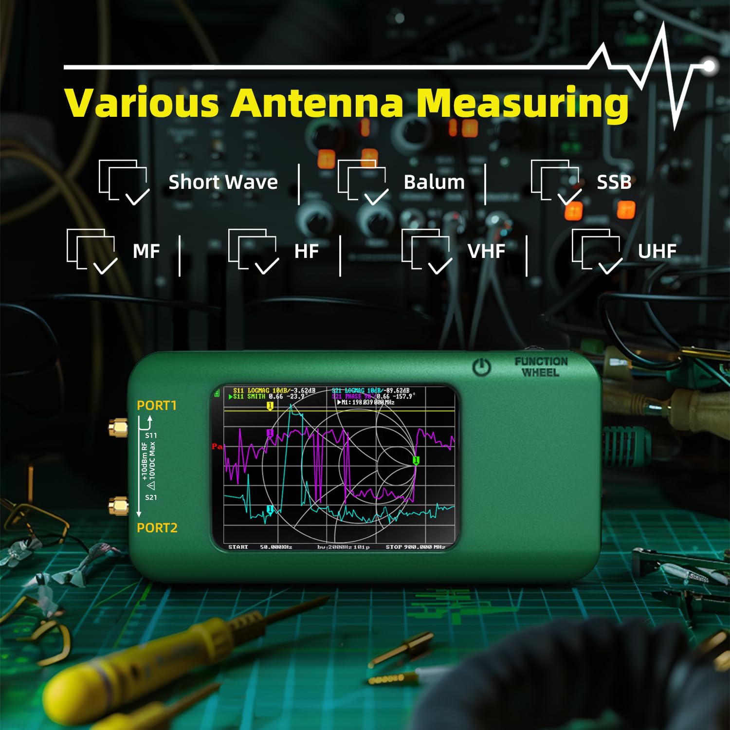
Figure 5.2: The analyzer's interface indicating its versatility in measuring various antenna types and frequency bands, including Short Wave, Balun, SSB, MF, HF, VHF, and UHF.
5.5 PC Connectivity
The analyzer can be connected to a PC via the USB-C port for advanced analysis, data logging, and firmware updates. Refer to the official BSIDE website for compatible PC software and drivers. When connected to a PC, the number of calibration and scanning points can be unlimited.
6. Maintenance
6.1 Cleaning
Wipe the device with a soft, dry cloth. For stubborn dirt, a slightly damp cloth with mild soap can be used, ensuring no liquid enters the ports or screen edges. Do not use abrasive cleaners or solvents.
6.2 Battery Care
- Avoid fully discharging the battery frequently.
- Store the device with a partial charge (around 50%) if not used for extended periods.
- Do not expose the device to extreme temperatures, as this can degrade battery life.
6.3 Storage
When not in use, store the analyzer in its protective silicone case in a cool, dry place, away from direct sunlight and excessive dust. The full-body soft silicone case provides protection against shocks, friction, and bumps.
7. Troubleshooting
- Device does not power on:
- Ensure the battery is charged. Connect to a power source and try again.
- Verify the power button is pressed and held for the correct duration.
- Inaccurate measurements:
- Perform a full calibration using the provided SHORT, OPEN, and LOAD standards.
- Check all cable connections for tightness and proper contact.
- Ensure the correct frequency range is set for your measurement.
- Screen is unresponsive:
- Try restarting the device.
- Ensure the screen is clean and free from debris.
- Cannot connect to PC:
- Verify the USB-C cable is functioning correctly.
- Install the necessary drivers and software from the BSIDE website.
8. Specifications
| Feature | Specification |
|---|---|
| Measurement Frequency | 10kHz ~ 1.5GHz |
| RF Output | 0dBm (±2dB, fundamental) |
| Frequency Accuracy | <2ppm |
| Frequency Stability | <0.5ppm |
| Measurement Range (Dynamic) | 70dB (50kHz-300MHz) / 60dB (300-900MHz) / 40dB (0.9G-1.5GHz) |
| Port SWR | <1.1 |
| Screen | 3.98-inch Color Screen (320*480) |
| Power | 3000mAh rechargeable Li-ion battery (built-in); Max charging current: 2A |
| Number of Calibration Points | Up to 401 (optional), unlimited when connecting to a PC |
| Number of Scanning Points | Up to 401 (optional), unlimited when connecting to a PC |
| Scanning Point Speed | >600 p/s (RBW=4000Hz) |
| Display Tracking | 4 |
| Mark | 8 |
| Set Save | 7 |
| Product Dimensions | 6.61 x 3.19 x 0.94 inches |
| Weight | 8.64 ounces |
9. Warranty and Support
BSIDE products are manufactured to high quality standards. For warranty information, please refer to the warranty card included with your product or visit the official BSIDE website. If you encounter any issues or require technical assistance, please contact BSIDE customer support through their official channels or your point of purchase. Please have your product model number and purchase date available when contacting support.