
1. Introduction
This manual provides detailed instructions for the installation, operation, and maintenance of the eletechsup 8CH DS18B20 Temperature Acquisition Module. This device is designed for industrial field signal collection and control, utilizing the RS485 MODBUS RTU communication protocol to acquire temperature data from up to eight DS18B20 sensors simultaneously.
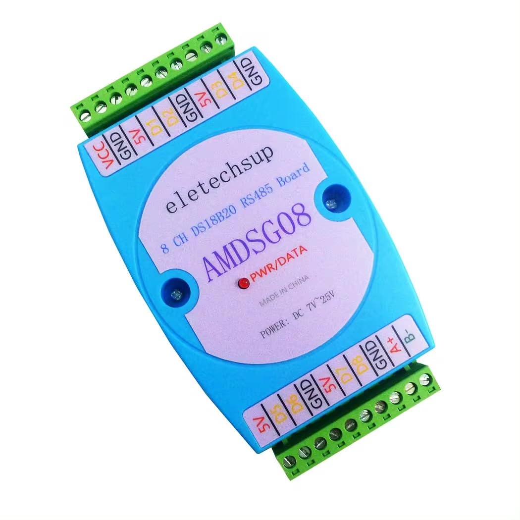
Figure 1: eletechsup 8CH DS18B20 Temperature Acquisition Module. This image displays the top view of the module, highlighting its compact design and connection terminals.
2. Product Features
- Supports 8-channel DS18B20 temperature sensor input.
- Utilizes standard RS485 MODBUS RTU communication protocol for networking with configuration software, PLCs, or industrial touch panels.
- Communication circuit designed with thunder protection and enhanced interference immunity.
- Suitable for signal collection and control in various industrial applications.
- Wide working voltage range: DC 7-30V (compatible with 9V, 12V, 24V systems).
- RS485 communication isolation protection up to 3000VDC.
- Standard DIN rail installation method.
3. Specifications
| Parameter | Value |
|---|---|
| Working Voltage | DC 7-30V (9V, 12V, 24V) |
| Working Current | 8-22mA |
| Sensor Type | DS18B20 (up to 8 sensors) |
| Temperature Range | -55°C to +125°C (-67°F to +257°F) |
| Temperature Accuracy | ±0.5°C (-10°C to 85°C) |
| RS485 Isolation Protection | 3000VDC |
| Communication Protocol | Standard MODBUS RTU |
| MODBUS Function Codes | 06/16 Write, 03/04 Read |
| Supported Baud Rates | 1200, 2400, 4800, 9600 (default), 19200, 38400, 57600, 115200 |
| Parity | No parity (default), Even parity, Odd parity |
| Installation Method | Standard DIN rail installation |
| Dimensions | 125 × 70 × 30mm |
| Weight | 114 grams |
4. Interface Definition
The module features clearly labeled terminals for power, DS18B20 sensor connections, and RS485 communication. Refer to the following definitions for proper wiring:
| Terminal | Description |
|---|---|
| VCC | Power input positive (+) |
| GND | Power input negative (-) |
| 5V | DS18B20 sensor power supply positive (+) |
| GND | DS18B20 sensor power supply negative (-) |
| D1 - D8 | DS18B20 channel 1 to 8 data ports |
| A+ | RS485 signal A+ |
| B- | RS485 signal B- |
5. Setup
Follow these steps to set up your 8CH DS18B20 Temperature Acquisition Module:
- Power Connection: Connect your DC 7-30V power supply to the VCC (+) and GND (-) terminals of the module. Ensure correct polarity to prevent damage.
- DS18B20 Sensor Connection: Connect each DS18B20 temperature sensor to its respective data port (D1 through D8). The 5V and GND terminals are provided for powering the DS18B20 sensors. Ensure all sensors are properly wired for power and data.
- RS485 Communication Connection: Connect the RS485 A+ terminal of the module to the A+ terminal of your MODBUS master device (e.g., PLC, industrial touch panel, or PC with RS485 converter). Connect the RS485 B- terminal of the module to the B- terminal of your MODBUS master device.
- DIN Rail Mounting: Mount the module securely onto a standard DIN rail using its integrated mounting mechanism.
6. Operating Instructions
The module operates using the standard MODBUS RTU protocol over an RS485 interface. Communication parameters such as baud rate and parity can be configured.
6.1. MODBUS RTU Communication
The module supports standard MODBUS RTU commands. Function codes 03 (Read Holding Registers) or 04 (Read Input Registers) are used to read temperature data from the connected DS18B20 sensors. Function codes 06 (Write Single Register) or 16 (Write Multiple Registers) can be used for configuration, if applicable (refer to specific MODBUS register map for details).
6.2. Reading Temperature Data
To read temperature values, send a MODBUS RTU read command to the module's assigned slave address. The module will respond with the temperature data from the active DS18B20 sensors. The temperature values are typically provided in a specific format (e.g., integer representing temperature multiplied by 10 or 100) which needs to be interpreted by the master device.
6.3. Configuration
Baud rate and parity settings can be adjusted via MODBUS commands. The default baud rate is 9600 bps with no parity. Consult the detailed MODBUS register map (not provided in this manual) for specific register addresses and values for configuration.
7. Maintenance
The 8CH DS18B20 Temperature Acquisition Module is designed for reliable operation with minimal maintenance. Follow these guidelines:
- Cleaning: Keep the module clean and free from dust and debris. Use a soft, dry cloth for cleaning. Do not use liquid cleaners or solvents.
- Environmental Conditions: Ensure the module operates within its specified temperature and humidity ranges. Avoid exposure to excessive moisture, corrosive gases, or strong vibrations.
- Wiring Inspection: Periodically check all wiring connections for tightness and integrity, especially in environments with vibration.
- Sensor Integrity: Inspect DS18B20 sensors and their wiring for any signs of damage or corrosion that could affect temperature readings.
8. Troubleshooting
If you encounter issues with the module, consider the following common problems and solutions:
- No Power Indication:
- Verify the power supply voltage is within the DC 7-30V range.
- Check power supply connections for correct polarity and secure contact.
- No Communication via RS485:
- Ensure RS485 A+ and B- connections are correct and not swapped.
- Verify that the baud rate, parity, and stop bits settings on the module and the master device match.
- Check the module's slave address to ensure it is unique and correctly configured in the master device.
- Inspect RS485 cabling for damage or improper termination.
- Incorrect Temperature Readings:
- Check DS18B20 sensor wiring for loose connections or damage.
- Ensure DS18B20 sensors are powered correctly from the 5V and GND terminals.
- Verify that the correct number of DS18B20 sensors are connected and recognized by the module.
- Confirm the interpretation of temperature data from the MODBUS registers in your master device's software.
9. Applications
The 8CH DS18B20 Temperature Acquisition Module is suitable for a variety of applications, including but not limited to:
- Thermostatic Controls
- Industrial Systems
- Consumer Products
- Thermometers
- Thermally Sensitive Systems
- Indoor and Outdoor Temperature Measurement
- Weather Forecasting and Monitoring
- Temperature Monitoring in Computer Rooms
- Warehouse Temperature Monitoring
- PLC Analog Expansion
- RS485 Networking Diagrams
10. Package Contents
The package includes the following items:
- 1 x DC 7-30V 8 Channel RS485 DS18B20 Temperature Collector (Model: AMDSG08)
11. Warranty and Support
For warranty information or technical support, please refer to the product's purchase documentation or contact your vendor. Keep your purchase receipt for warranty claims. For additional information or specific technical inquiries, please visit the eletechsup official website or contact their customer service department.
