1. Introduction
This manual provides essential information for the safe and efficient operation of your EDECOA 2000W 12V Pure Sine Wave Power Inverter. Please read it thoroughly before installation and use, and retain it for future reference.
1.1 Product Overview
The EDECOA 2000W 12V Pure Sine Wave Power Inverter converts 12V DC battery power into 110V/120V AC household power. It delivers 2000W of continuous power and 4000W of peak surge power, suitable for various applications including home, truck, and RV use. The pure sine wave output ensures compatibility with sensitive electronics.

Image 1.1: EDECOA 2000W 12V Pure Sine Wave Power Inverter with included cables and remote controller.
1.2 What's in the Box
- EDECOA 2000 watts 12V pure sine wave inverter
- One pair of 3AWG 23.6in flexible battery cables (red and black)
- ET-RC remote controller
- User manual
- Installation bag (containing mounting hardware)

Image 1.2: All components included in the EDECOA 2000W inverter package: the inverter unit, battery cables, and the ET-RC remote controller.
2. Safety Information
Always observe the following safety precautions to prevent injury or damage to the inverter and connected devices.
- Electrical Shock Hazard: Do not open the inverter casing. There are no user-serviceable parts inside. High voltage is present.
- Fire Hazard: Do not install the inverter near flammable materials or in areas with explosive gases. Ensure adequate ventilation.
- Battery Safety: Connect the inverter only to 12V DC batteries. Ensure correct polarity (+ to + and - to -). Reversing polarity will damage the inverter.
- Ventilation: Ensure the inverter has sufficient airflow around it. Do not block ventilation openings.
- Moisture: Do not expose the inverter to rain, moisture, or liquids.
- Overload: Do not exceed the inverter's continuous power rating (2000W) or peak surge power (4000W).
- Grounding: The inverter must be properly grounded.
- Children: Keep the inverter out of reach of children.
3. Product Features
The EDECOA 2000W inverter incorporates several design and technological features for optimal performance and user convenience.
3.1 Performance and Efficiency
- Converts 12V DC to 110V AC.
- Provides 2000W continuous power and 4000W peak surge power.
- Generates a pure sine wave output at 120VAC.
- Conversion efficiency exceeds 90%, minimizing energy loss.
3.2 Design and Control
- Features three US-standard AC outlets.
- Includes an ET-RC remote control for convenient operation. The remote allows turning the inverter on/off, monitoring input/output voltage, battery capacity, and frequency.
- Integrated intelligent alarm system displays problem reasons on the remote control screen when the inverter enters a protective state.
- Fan status and temperature are also displayed on the remote control.

Image 3.1: The ET-RC remote controller allows convenient operation and monitoring of the inverter's status from a distance.
3.3 Advanced Technology
- Utilizes SPWM (Sine Pulse Width Modulation) system to reduce interruptions and optimize recovery times.
- Soft start system for gradual power delivery.
- Automatic start function.
- Galvanic isolation system between DC and AC for enhanced safety.
3.4 Protection Features
- Automatic Voltage Regulation (AVR).
- Intelligent Power Management (IPM).
- Intelligent Fan Control (IFC) for efficient cooling.
- Built-in fuse for device protection.
- Protections against overheating, under-voltage, over-voltage, and short-circuiting.
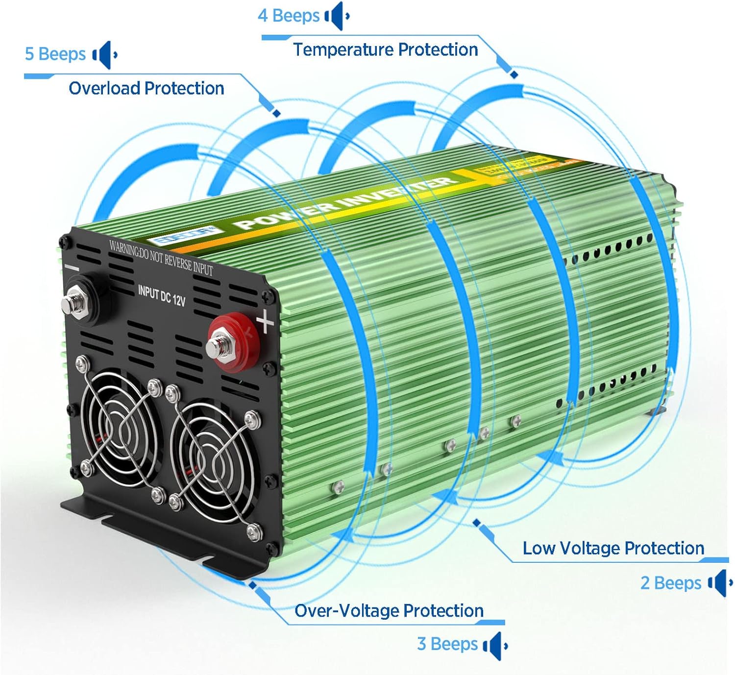
Image 3.2: Visual representation of the inverter's protection features, including low voltage, over-voltage, overload, and temperature protection, indicated by audible beeps.

Image 3.3: The inverter features dual cooling fans and an aluminum casing for effective heat dissipation, ensuring quiet operation.
4. Components Overview
Familiarize yourself with the various parts of the inverter and its remote control.
4.1 Inverter Unit

Image 4.1: Front and rear panels of the inverter, highlighting key components.
- Input DC 12V Terminals: Red for positive (+), Black for negative (-). Made of pure copper.
- Intelligent Cooling Fans: Located on the rear panel for heat dissipation.
- Ground Wire Port: For connecting the inverter to an earth ground.
- AC Outlets: Three US-standard 120V AC outlets on the front panel.
- Power Switch: ON/OFF toggle switch for the inverter.
- RJ45 Remote Port: For connecting the ET-RC remote controller.
- Work and Error Indicator: LED light indicating operational status or fault conditions.
4.2 ET-RC Remote Controller

Image 4.2: Detailed view of the ET-RC remote controller display and its various indicators and controls.
- Power Switch (ON/OFF)
- Dual USB Ports (5V, 2.1A)
- Alarm Indicator
- Over-temperature Protection Indicator
- Low Input Voltage Indicator
- Battery Capacity Display
- High Input Voltage Indicator
- AC Output Voltage Display
- DC Input Voltage Display
- Overload Protection Indicator
- Wattage of Appliances Display (Load)
- Fan Working Status Indicator
- Frequency Display (Hz)
- RJ45 Interface (for connection to inverter)
5. Setup and Installation
Proper installation is crucial for the safe and efficient operation of your inverter. Ensure the installation location is dry, well-ventilated, and away from direct sunlight or heat sources.
5.1 Choosing a Location
- Mount the inverter on a flat, stable surface.
- Allow at least 6 inches of clear space around the inverter for proper ventilation.
- Avoid areas where dust, dirt, or moisture can accumulate.
- Keep away from children and unauthorized personnel.
5.2 Battery Connection
The inverter is designed for 12V DC battery systems. Ensure your battery bank provides a stable 12V DC output.
- Ensure the inverter's power switch is in the OFF position.
- Connect the red battery cable to the positive (+) terminal of your 12V battery and to the red (+) terminal on the inverter.
- Connect the black battery cable to the negative (-) terminal of your 12V battery and to the black (-) terminal on the inverter.
- Ensure all connections are tight and secure to prevent arcing and overheating.
- Important: Do not reverse polarity. This will cause severe damage to the inverter and void the warranty.
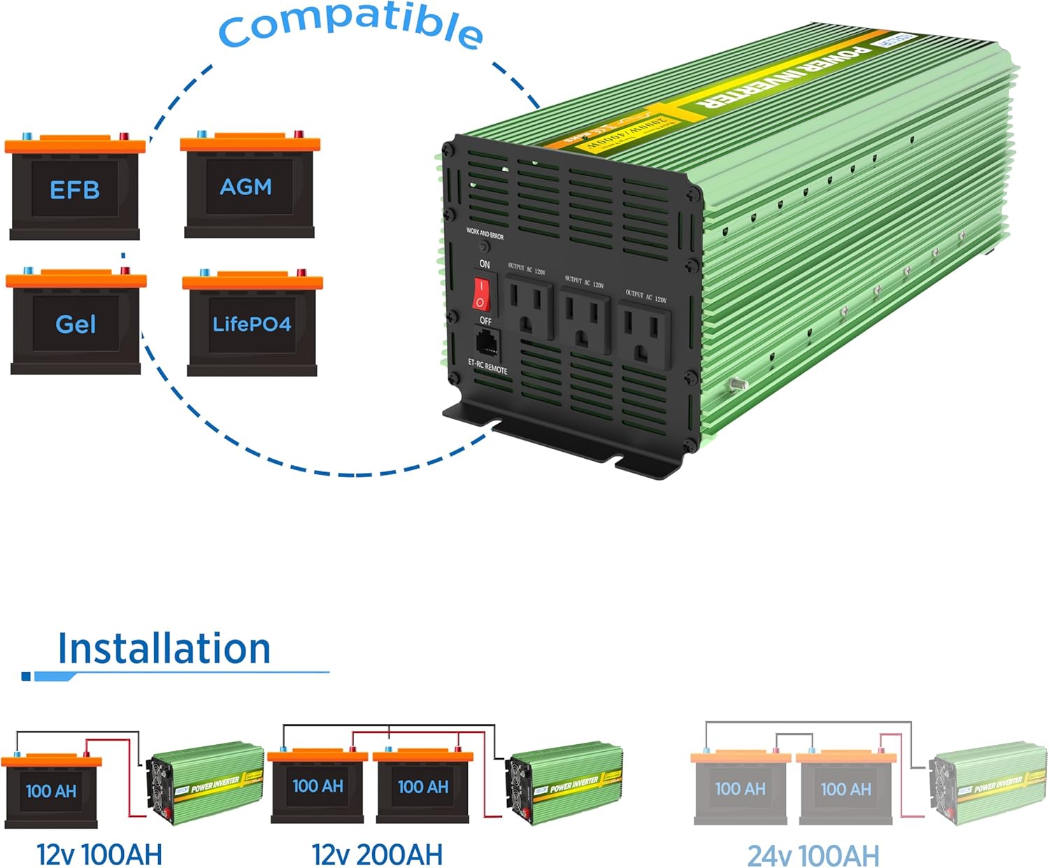
Image 5.1: The inverter is compatible with various 12V battery types (EFB, AGM, Gel, LiFePO4). Diagrams illustrate proper battery connections for 12V 100AH and 12V 200AH configurations.
The inverter can be integrated into various power systems, including solar setups or directly with a car battery. Always ensure the battery system matches the inverter's 12V DC input requirement.

Image 5.2: Diagram showing two common installation options: connecting the inverter to a solar power system with a battery and controller, or directly to a car battery.
5.3 Grounding the Inverter
Connect the inverter's ground terminal to a reliable earth ground. This is a critical safety step to prevent electrical shock.
5.4 Remote Controller Connection
Connect the ET-RC remote controller to the RJ45 port on the inverter using the provided 4-meter standard network cable (RJ45).
6. Operating Instructions
Follow these steps to operate your EDECOA power inverter.
6.1 Powering On the Inverter
- Ensure all DC connections are secure and correct.
- Flip the ON/OFF switch on the inverter (or on the remote controller) to the "ON" position.
- The "WORK" indicator light on the inverter will illuminate, and the remote controller display will activate, showing current status.
6.2 Connecting AC Devices
- Plug your AC devices into the 120V AC outlets on the front of the inverter.
- Ensure the total wattage of all connected devices does not exceed 2000W continuously. For devices with high startup surge, ensure the combined surge power does not exceed 4000W.
- For USB charging, connect devices to the 5V/2.1A USB ports on the remote controller.

Image 6.1: The EDECOA inverter in operation, providing AC power to a coffee maker, demonstrating its use in a household setting.
6.3 Monitoring with the Remote Controller
The ET-RC remote controller provides real-time information about the inverter's status:
- Battery Capacity: Displays the remaining battery charge.
- Input Voltage: Shows the DC voltage from the battery.
- Output Voltage: Indicates the AC voltage being supplied (120V).
- Frequency: Displays the output frequency (60Hz).
- Load: Shows the current power consumption of connected appliances.
- Fan Status: Indicates if the cooling fans are active.
- Protection Indicators: Icons will appear for over-temperature, low input voltage, high input voltage, and overload conditions.
6.4 Powering Off the Inverter
- Disconnect all AC devices from the inverter outlets.
- Flip the ON/OFF switch on the inverter (or remote controller) to the "OFF" position.
- The "WORK" indicator will turn off, and the remote display will go blank.
7. Maintenance
Regular maintenance ensures the longevity and optimal performance of your inverter.
- Cleaning: Periodically clean the exterior of the inverter with a dry, soft cloth. Do not use liquids or abrasive cleaners.
- Ventilation: Ensure the cooling vents are free from dust and debris. Use compressed air to clear blockages if necessary.
- Connections: Regularly check battery cable connections for tightness and corrosion. Clean any corrosion with a wire brush and baking soda solution.
- Storage: If storing the inverter for an extended period, disconnect it from the battery and store it in a cool, dry place.
8. Troubleshooting
This section addresses common issues and their solutions. The intelligent alarm system on the ET-RC remote controller will display specific icons indicating the problem.
| Problem/Alarm Indication | Possible Cause | Solution |
|---|---|---|
| No output voltage / Inverter not turning on | Loose battery connections, low battery voltage, inverter switch off, internal fuse blown. | Check battery connections. Charge or replace battery. Ensure inverter switch is ON. Contact support if fuse is suspected. |
| Low Input Voltage Alarm (Icon on remote, 2 beeps) | Battery voltage is too low. | Charge or replace the battery. Disconnect loads to prevent deep discharge. |
| High Input Voltage Alarm (Icon on remote) | Battery voltage is too high. | Check battery charging system. Ensure battery voltage is within 12V specifications. |
| Overload Protection Alarm (Icon on remote, 5 beeps) | Connected load exceeds inverter's continuous or surge rating. | Reduce the total load by disconnecting some appliances. Restart the inverter. |
| Over-temperature Protection Alarm (Icon on remote, 4 beeps) | Inverter is overheating due to poor ventilation or excessive load. | Ensure adequate ventilation. Reduce load. Allow inverter to cool down before restarting. |
| Inverter fans not operating | Normal operation at low load/temperature, or fan malfunction. | Fans are intelligently controlled and only activate when needed. If inverter is hot and fans are off, contact support. |
9. Specifications
| Parameter | Value |
|---|---|
| Model Name | 2000W-12V |
| Continuous Power | 2000 Watts |
| Peak Surge Power | 4000 Watts |
| Input DC Voltage | 12V DC |
| Output AC Voltage | 110V / 120V AC |
| Output Waveform | Pure Sine Wave |
| Output Frequency | 60Hz |
| Conversion Efficiency | >90% |
| USB Output | 2 x 5V/2.1A |
| Product Dimensions | 17.5 x 8.5 x 7.3 inches |
| Item Weight | 8.42 pounds |
| Power Source | Solar and Battery Powered |
| Manufacturer | EDECOA |
10. Warranty and Support
For warranty information, technical support, or service inquiries, please refer to the official EDECOA website or contact their customer service directly. The user manual included in your package may contain specific warranty details.
You can visit the EDECOA Store on Amazon for more product information: EDECOA Store


