
1. Introduction
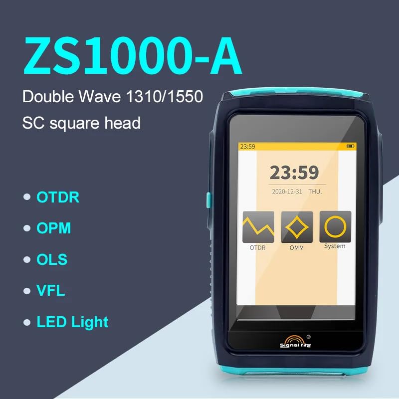
This manual provides detailed instructions for the safe and effective use of the Musksulod Signal Fire-Optical Fiber OTDR Reflectometer Model ZS1000-A. The ZS1000-A is a compact, multi-functional optical time-domain reflectometer designed for testing and maintaining fiber optic networks. It features dual-wave 1310/1550nm capabilities and an SC square head connector, making it suitable for a variety of fiber optic applications.
2. Safety Information
Please read and understand all safety warnings and operating instructions before using this device. Failure to do so may result in injury or damage to the equipment.
- Optical Safety: Never look directly into the optical output ports when the device is active. Invisible laser radiation can cause severe eye damage. Always use appropriate eye protection when working with fiber optic equipment.
- Electrical Safety: Use only the provided charger and power adapter. Do not operate the device in wet or damp conditions. Avoid disassembling the device, as it contains no user-serviceable parts and may expose you to electrical hazards.
- Battery Safety: The device uses a rechargeable battery. Do not expose the battery to extreme temperatures, puncture, or incinerate it. Dispose of batteries according to local regulations.
- Handling: Handle the device with care. Avoid dropping or subjecting it to strong impacts. Keep the optical connectors clean to ensure accurate measurements.
3. Product Overview
The Musksulod Signal Fire-Optical Fiber OTDR Reflectometer ZS1000-A is a portable, high-performance device integrating multiple functions for fiber optic testing.
3.1 Key Features
- Model ZS1000-A: Dual-wave operation at 1310nm and 1550nm, equipped with an SC square head connector.
- Multi-functional: Integrates OTDR (Optical Time-Domain Reflectometer), OPM (Optical Power Meter), OLS (Optical Light Source), VFL (Visual Fault Locator), and LED Light functions.
- Measurement Range: Capable of accurate measurements up to 80km.
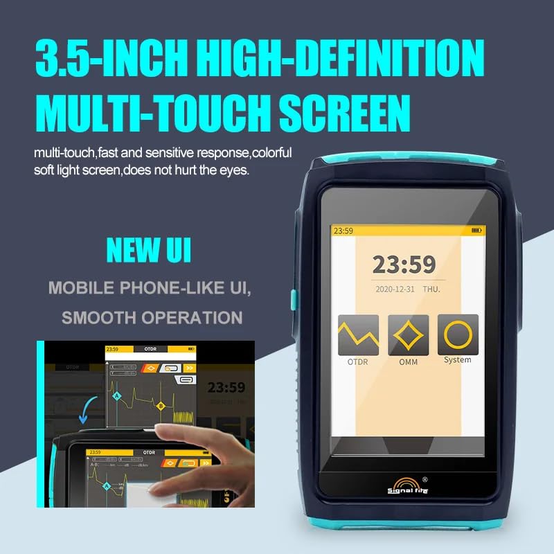
- Display: Features a 3.5-inch high-definition multi-touch screen with a user-friendly, mobile phone-like interface for smooth operation.
- Portability: Compact 'Mini' design, allowing for easy one-handed operation.
- Protected Interfaces: All interfaces, including OTDR, VFL, OPM, USB, and Type-C, are hidden under protective covers to ensure dust-proof operation and durability. The Type-C interface is compatible with standard mobile phone chargers.
3.2 Device Components

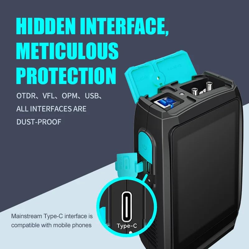
The device typically includes:
- 3.5-inch Multi-Touch Screen: For displaying test results and navigating the user interface.
- Control Buttons: Minimal physical buttons, primarily relying on the touch screen.
- Optical Ports: Dedicated ports for OTDR, OPM, OLS, and VFL functions, typically with SC square head connectors for the ZS1000-A model.
- USB Port: For data transfer.
- Type-C Port: For charging and data transfer.
- LED Light: Integrated for illumination in dark environments.
4. Setup
4.1 Unpacking
Carefully unpack the OTDR device and all accessories. Verify that all components listed in the packing list are present and undamaged. Retain the original packaging for future storage or transport.
4.2 Charging the Battery
Before first use, fully charge the device's internal battery. Connect the provided Type-C USB cable to the device's Type-C port (located under a protective cover on the side) and plug the other end into a compatible USB power adapter. The charging indicator on the screen will show the charging status. A full charge typically takes several hours.
4.3 Powering On/Off
- Power On: Press and hold the power button (usually located on the side) for a few seconds until the screen illuminates and the device boots up.
- Power Off: Press and hold the power button until a power-off prompt appears on the screen. Follow the on-screen instructions to confirm shutdown. A short press typically puts the device into sleep mode.
5. Operating Instructions
The ZS1000-A features a mobile phone-like UI for intuitive navigation. Tap icons to select functions.
5.1 Navigating the User Interface
Upon powering on, the main menu will display icons for OTDR, OMM (Optical Multi-Meter, which includes OPM and OLS functions), and System settings. Tap the desired icon to enter that function's interface.
5.2 OTDR Measurement
- Clean Connectors: Ensure all fiber optic connectors are clean before connecting them to the OTDR port. Use appropriate fiber cleaning tools.
- Connect Fiber: Open the protective cover and connect the fiber under test to the OTDR port. Ensure a secure connection.
- Select OTDR Function: From the main menu, tap the 'OTDR' icon.
- Set Parameters: On the OTDR screen, configure parameters such as wavelength (1310nm or 1550nm), range, pulse width, and measurement mode (e.g., auto, manual). For ZS1000-A, both 1310nm and 1550nm are available.
- Start Measurement: Tap the 'Start' or 'Measure' button to begin the OTDR trace. The device will display the trace graph and event table.
- Analyze Results: Review the trace for events like splices, connectors, and fiber breaks. The event table provides detailed information on each event.
- Save Data: Save the measurement results for later analysis or reporting.
5.3 Optical Power Meter (OPM) Function
- Connect Fiber: Connect the fiber to be measured to the OPM port.
- Select OMM/OPM: From the main menu, tap 'OMM', then select the OPM function.
- Set Wavelength: Select the appropriate wavelength for the incoming optical signal.
- Read Power: The screen will display the optical power in dBm or mW.
5.4 Optical Light Source (OLS) Function
- Connect Fiber: Connect the fiber to the OLS port.
- Select OMM/OLS: From the main menu, tap 'OMM', then select the OLS function.
- Set Wavelength: Select the desired output wavelength (e.g., 1310nm or 1550nm).
- Activate Source: Activate the light source. The device will emit a continuous wave (CW) or modulated signal.
5.5 Visual Fault Locator (VFL) Function
- Connect Fiber: Connect the fiber to the VFL port.
- Activate VFL: Select the VFL function from the menu. The VFL port will emit a visible red laser light.
- Locate Faults: Observe the fiber for light leakage at breaks, tight bends, or faulty connectors.
5.6 LED Light Function
The integrated LED light can be activated from the system settings or a dedicated button/icon to provide illumination in dark working environments.
6. Maintenance
6.1 Cleaning the Device
- Exterior: Use a soft, dry, lint-free cloth to clean the exterior of the device. For stubborn dirt, a slightly damp cloth with mild detergent can be used, ensuring no liquid enters the ports.
- Screen: Use a screen-specific cleaning solution and a microfiber cloth to clean the touch screen.
- Optical Ports: Clean optical ports regularly using specialized fiber optic cleaning tools (e.g., fiber cleaning sticks, lint-free wipes with isopropyl alcohol). Contaminated connectors are a primary cause of inaccurate measurements. Always ensure the device is off and no laser is active before cleaning optical ports.
6.2 Battery Care
- To prolong battery life, avoid fully discharging the battery frequently.
- If storing the device for an extended period, charge the battery to approximately 50-70% and recharge every few months.
- Avoid exposing the device to extreme temperatures, which can degrade battery performance.
6.3 Storage
Store the device in a cool, dry place, away from direct sunlight and extreme temperatures. Use the original packaging or a protective case to prevent physical damage and dust accumulation.
7. Troubleshooting
| Problem | Possible Cause | Solution |
|---|---|---|
| Device does not power on | Low battery; Faulty power button; Device malfunction | Charge the battery fully. Ensure the power button is pressed correctly. If problem persists, contact support. |
| Inaccurate OTDR readings | Dirty optical connectors; Incorrect parameters; Damaged fiber | Clean all optical connectors thoroughly. Verify OTDR parameters (wavelength, range, pulse width). Inspect the fiber for damage. |
| No VFL light output | VFL not activated; Dirty VFL port; Internal fault | Ensure VFL function is selected. Clean the VFL port. If still no output, contact support. |
| Touch screen unresponsive | Software glitch; Screen damage | Restart the device. If unresponsive, contact support. |
8. Specifications
| Feature | Specification |
|---|---|
| Model | ZS1000-A |
| Wavelengths | 1310nm / 1550nm (Dual Wave) |
| Connector Type | SC Square Head |
| Measurement Range | Up to 80km |
| Functions | OTDR, OPM, OLS, VFL, LED Light |
| Display | 3.5-inch High-Definition Multi-Touch Screen |
| Power Source | Battery Powered (Internal Rechargeable) |
| Charging Interface | Type-C USB |
| Manufacturer | Musksulod |
| ASIN | B0DB5NMC1Y |
| UPC | 749691937638 |
9. Warranty and Support
This product comes with a standard manufacturer's warranty. For specific warranty terms, please refer to the documentation included with your purchase or contact the retailer. For technical support, troubleshooting assistance beyond this manual, or service inquiries, please contact Musksulod customer service or your authorized dealer.