
1. Introduction
This manual provides essential information for the safe and efficient installation, operation, and maintenance of the CSCPEXCZ SU600 series Variable Frequency Drive (VFD). The SU600 VFD is designed to control the speed and torque of three-phase AC induction motors by varying the frequency and voltage of the power supplied to the motor. Please read this manual thoroughly before installation and operation to ensure proper usage and to prevent potential hazards.
2. Safety Information
WARNING: Improper installation or operation can lead to serious injury or death, and damage to equipment. Only qualified personnel should install, operate, and maintain this device.
- Always disconnect power before performing any wiring or maintenance. Wait at least 5 minutes after power-off for capacitors to discharge.
- Ensure proper grounding of the VFD and the motor.
- Do not touch electrical components when power is applied.
- Verify that the input voltage matches the VFD's rated voltage.
- Install the VFD in a clean, dry, and well-ventilated environment, away from direct sunlight, corrosive gases, and flammable materials.
- Use appropriate personal protective equipment (PPE) during installation and maintenance.
3. Product Overview
The CSCPEXCZ SU600 VFD is a robust frequency converter designed for industrial applications. It features a main board with enhanced protection against environmental factors.
3.1 Main Board Characteristics

Image: Internal view of the SU600 VFD, highlighting the main circuit board and its protective features.
- Waterproof: Provides protection against water ingress.
- Moisture Proof: Designed to resist damage from humidity.
- Mildew Proof: Prevents the growth of mold and mildew on internal components.
3.2 Control Panel and Interface
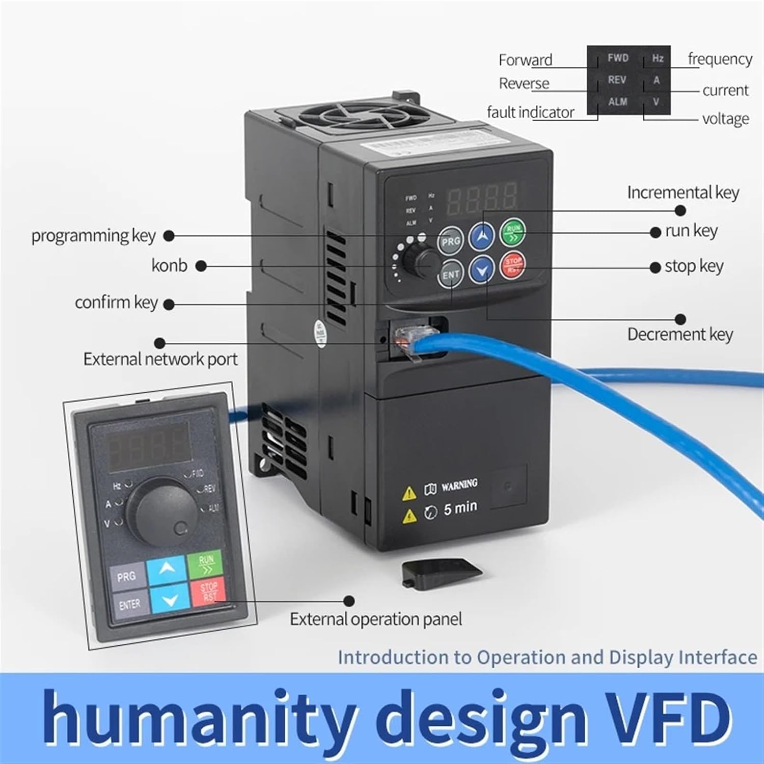
Image: Front panel of the SU600 VFD, illustrating the display and control buttons, along with an external operation panel.
- Display: Shows operational parameters such as frequency, current, and voltage.
- Programming Key (PRG): Used to enter and exit programming mode.
- Incremental Key (UP arrow): Increases parameter values or navigates menus.
- Decrement Key (DOWN arrow): Decreases parameter values or navigates menus.
- Confirm Key (ENT): Confirms selections and saves parameter settings.
- Run Key (RUN): Starts the motor operation.
- Stop Key (STOP/RST): Stops the motor operation and resets faults.
- External Network Port: For communication with external control systems.
- External Operation Panel: An optional remote control panel for flexible operation.

Image: Detailed view of the external operation panel, showing its compact design and dimensions (79mm x 53mm).
4. Specifications
The following table outlines the key technical specifications for the SU600-3R7G3 VFD model.

Image: Detailed product parameters for the SU600-3R7G3 VFD.
| Parameter | Value |
|---|---|
| Model | SU600-3R7G3 |
| Adapted Motor Power | 3.7KW (5HP) |
| Input Voltage | Three-phase 380V |
| Output Voltage | Three-phase 380V |
| Rated Output Current | 9A |
| Dimensions (L x W x H) | 185mm x 87mm x 138mm |
| Weight | 1.16kg |
5. Setup and Installation
Proper installation is crucial for the safe and reliable operation of the VFD. Ensure all connections are secure and comply with local electrical codes.
5.1 Wiring Diagram

Image: Comprehensive wiring diagram for the SU600 VFD, detailing power input, motor output, and brake resistor connections.
- Input Power Connection (R, S/L1, T/L2): Connect the three-phase 380V AC power supply to these terminals. An appropriate circuit breaker should be installed upstream for protection.
- Output Power Connection (U, V, W): Connect the three-phase motor to these terminals. Ensure correct phase sequence for desired motor rotation.
- Ground Wire: Connect the ground terminal to a reliable earth ground. This is essential for safety.
- Brake Resistor Connection (P+, PB): For applications requiring rapid deceleration or braking, connect an external brake resistor between P+ and PB terminals. (Note: This is an optional connection, typically for CNC machine tool selection or similar high-inertia loads.)
5.2 Physical Installation
Mount the VFD vertically on a stable, non-flammable surface. Ensure adequate clearance around the unit for proper ventilation and heat dissipation. Avoid mounting in areas with excessive vibration, dust, or moisture.
6. Operating Instructions
After successful installation and wiring, the VFD is ready for operation. Refer to the control panel section for button functions.
- Power On: Apply power to the VFD. The display should illuminate.
- Parameter Setting (Optional): If specific motor parameters or control modes are required, press the PRG key to enter programming mode. Use the UP/DOWN arrows to navigate parameters and ENT to confirm. Refer to the detailed programming manual for specific parameter codes.
- Start Motor: Press the RUN key to start the motor. The VFD will accelerate the motor to the set frequency.
- Adjust Frequency: Use the UP/DOWN arrows to adjust the output frequency (motor speed) during operation.
- Stop Motor: Press the STOP/RST key to stop the motor. The VFD will decelerate the motor to a stop.
7. Maintenance
Regular maintenance ensures the longevity and optimal performance of your VFD.
- Cleaning: Periodically clean the VFD's exterior and cooling fins to prevent dust accumulation, which can hinder heat dissipation. Use a soft, dry cloth. Do not use liquid cleaners.
- Fan Inspection: Check the cooling fan for proper operation and ensure it is free from obstructions. Replace if noisy or not functioning correctly.
- Terminal Connections: Annually, inspect all terminal connections for tightness. Loose connections can cause overheating and damage.
- Environmental Check: Ensure the operating environment remains within specified temperature and humidity ranges.
8. Troubleshooting
This section provides solutions for common issues. For complex problems, contact technical support.
| Problem | Possible Cause | Solution |
|---|---|---|
| VFD does not power on | No input power; Blown fuse/breaker | Check power supply; Inspect fuses/breakers |
| Motor does not run | Incorrect wiring; Fault condition; Parameter error | Verify wiring; Check display for fault codes; Review motor parameters |
| Overcurrent fault | Motor overload; Short circuit; Acceleration time too short | Reduce load; Check motor/cables; Increase acceleration time parameter |
| Overvoltage fault | High input voltage; Deceleration time too short; Regenerative load | Check input voltage; Increase deceleration time; Install brake resistor if needed |
9. Warranty and Support
This CSCPEXCZ VFD product is covered by a standard manufacturer's warranty against defects in materials and workmanship. For specific warranty terms, duration, and conditions, please refer to the warranty card included with your product or contact your point of purchase.
For technical assistance, troubleshooting beyond this manual, or spare parts inquiries, please contact CSCPEXCZ customer support or your authorized distributor. When contacting support, please have your product model number (SU600-3R7G3) and purchase information readily available.