1. Product Overview
This kit provides components to assemble a 24-hour digital circuit clock. It utilizes CD4518, CD4511, CD4081, CD4013, and CD4060 integrated circuits. The design does not incorporate a microcontroller, meaning there is no programmable software. The clock allows for calibration of hours, minutes, and seconds, but it does not include an alarm function.
The clock's functionality is primarily driven by a second signal generator, a counter, a decoding display, and a time calibration circuit. A precise 1Hz square wave signal, derived from a high-frequency signal generator, ensures accurate timekeeping. The second signal generator is composed of CD4060 and CD4013 chips. The CD4060 acts as a 14-level binary frequency divider/oscillator, generating a 2Hz square wave signal. The CD4013, configured as a binary counter, then processes this signal to produce the 1Hz second signal.
Three CD4518 chips are used for counting hours, minutes, and seconds. Minutes and seconds are configured for 60-binary counting, while hours are set for 24-binary. The CD4518 outputs BCD code to the CD4511 BCD decoder, which then converts it into segment codes for the digital tube display, visually presenting the current time. The red digital tubes offer clear visibility.
2. Kit Contents
The following components are included in your DIY kit:
- PCB board X1
- 0.56 digital tube 1 bit common negative X6
- 470 ohm resistor X2
- 1K resistor X50
- 2.2K resistor X3
- 100K Resistor X1
- 10M resistor X1
- 1N4148 Diode X4
- 103 Monolithic Capacitor X3
- 32.768KHZ crystal X1
- 30P Porcelain Chip Capacitor X2
- 25V 100UF Capacitor X1
- KF301-2PX1
- 6*6*5 Keypad X1
- 12D07 Toggle Switch X1
- 16P IC Block X10
- 14P IC Block X 2
- CD4511 X6
- CD4518 X3
- CD4081 X1
- CD4060 X1
- CD4013 X1
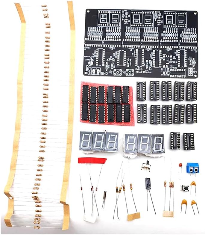
Image: All components included in the kit, ready for assembly.
3. Assembly Instructions
This kit requires soldering and hands-on electronic assembly skills. Please review all components and the circuit diagram before beginning. It is generally recommended to start by soldering the shortest components first and then proceed to taller ones.
3.1. Component Placement and Soldering
- Prepare the PCB: Ensure the Printed Circuit Board (PCB) is clean and free of debris. Identify all component locations as marked on the silkscreen.
- Solder Resistors: Begin by soldering all resistors (470 ohm, 1K, 2.2K, 100K, 10M) into their designated positions. Pay attention to the resistor values and their corresponding labels (e.g., R1, R2).
- Solder Diodes: Solder the 1N4148 diodes, ensuring correct polarity (the band on the diode matches the band on the PCB silkscreen).
- Install IC Sockets: Solder the 16P and 14P IC blocks (sockets) onto the PCB. These sockets will hold the integrated circuits. Ensure they are oriented correctly.
- Solder Capacitors: Solder the 103 monolithic capacitors, 30P porcelain chip capacitors, and the 25V 100UF electrolytic capacitor. For the electrolytic capacitor, observe polarity (the longer lead is positive, and the negative side is usually marked on the capacitor body and PCB).
- Install Crystal Oscillator: Solder the 32.768KHZ crystal oscillator.
- Solder Keypads and Switch: Solder the 6*6*5 keypad and the 12D07 toggle switch.
- Install Digital Tubes: Carefully solder the 0.56 digital tubes (common negative) into their positions. Ensure correct orientation.
- Install Integrated Circuits (ICs): Once all other components are soldered, carefully insert the CD4511, CD4518, CD4081, CD4060, and CD4013 ICs into their respective sockets. Ensure the notch on the IC aligns with the notch on the socket and the PCB silkscreen.
- Connect Power Terminal: Solder the KF301-2P terminal for power input.
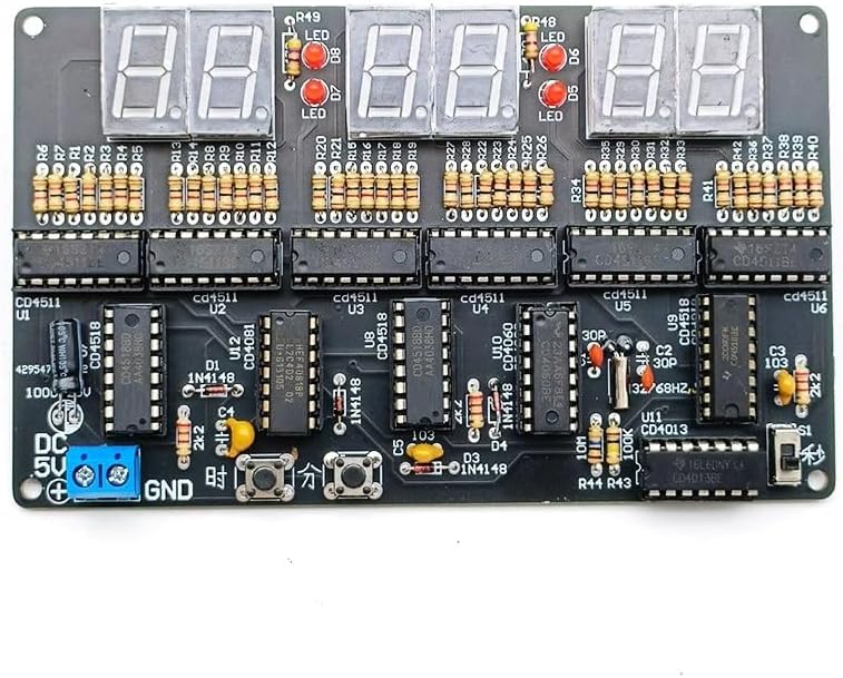
Image: The fully assembled Printed Circuit Board (PCB) with all components soldered.
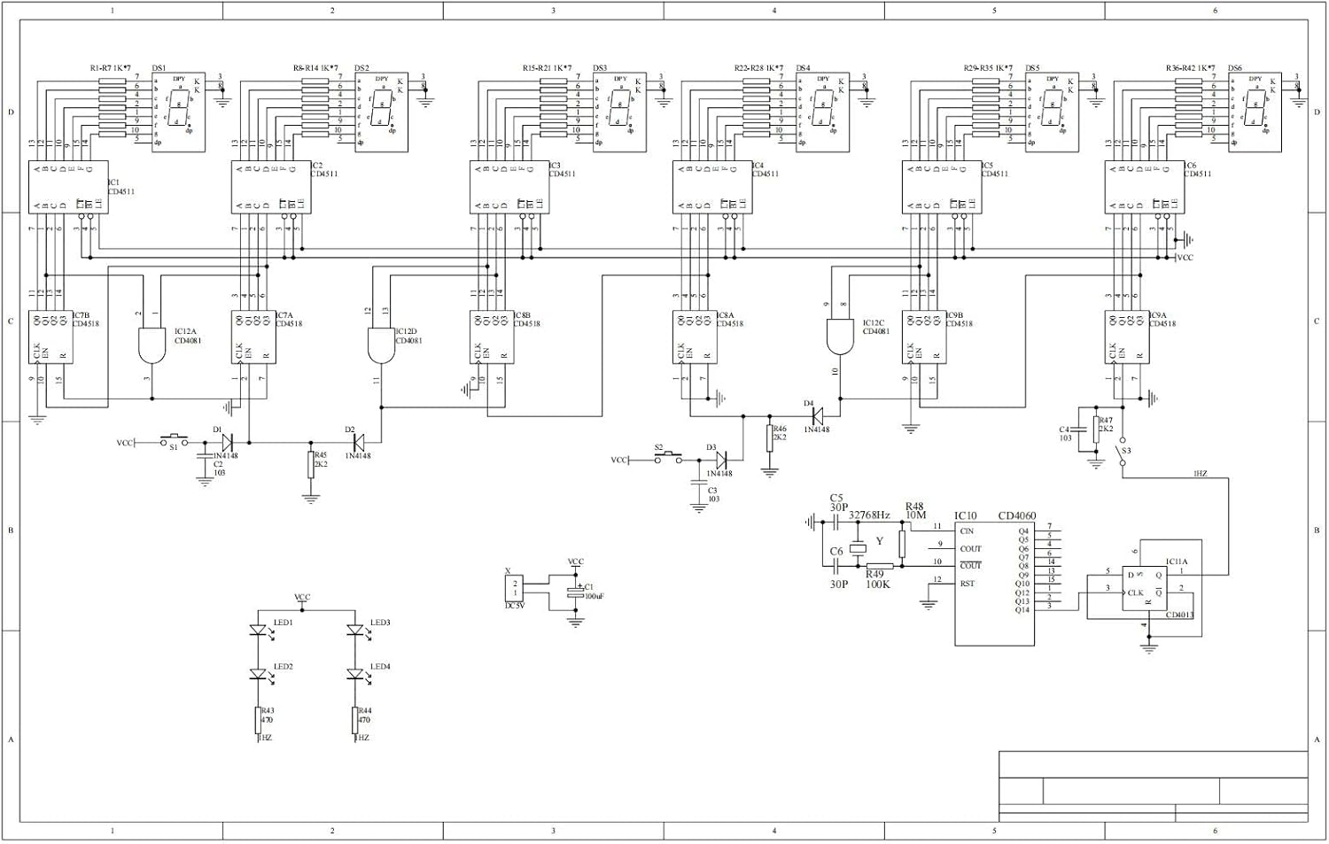
Image: Detailed circuit schematic diagram for reference during assembly and troubleshooting.
3.2. Assembly Demonstration Videos
Video: A demonstration of the soldering process for a 6-digit clock kit, showing component placement and soldering techniques. This video is provided by ETAxopowo.
Video: This video from IC-Board demonstrates the functional operation and assembly of a DIY clock soldering kit, including component installation and initial power-up.
4. Operating Instructions
After successful assembly, connect the clock to a DC 4.5V-5.5V power source via the KF301-2P terminal. The clock will display the time on its red digital tubes.
4.1. Time Calibration
The clock allows for calibration of hours, minutes, and seconds using the onboard buttons. Refer to the circuit diagram for specific button functions (typically labeled for adjustment).
- Adjusting Hours: Press the designated button to enter hour adjustment mode. Use the increment/decrement buttons to set the correct hour.
- Adjusting Minutes: Press the designated button to enter minute adjustment mode. Use the increment/decrement buttons to set the correct minute.
- Adjusting Seconds: Press the designated button to enter second adjustment mode. Use the increment/decrement buttons to set the correct second.
This clock operates in a 24-hour format and does not feature an alarm function.
4.2. Operation Demonstration Video
Video: This video demonstrates the basic operation of the DC 4.5V-5.5V 6-bit Digital Circuit Clock kit, including initial power-up and time adjustment. This video is provided by DIY-Module.
5. Maintenance
- Keep the assembled clock in a dry environment to prevent moisture damage to electronic components.
- Avoid exposing the clock to extreme temperatures or direct sunlight for prolonged periods.
- Clean the digital display and casing with a soft, dry cloth. Do not use abrasive cleaners or solvents.
- Ensure the power supply is within the specified 4.5V-5.5V DC range to prevent damage.
6. Troubleshooting
- Clock does not power on:
- Verify the power supply is connected correctly and providing the specified voltage (DC 4.5V-5.5V).
- Check all power connections and solder joints for continuity and proper contact.
- Ensure the toggle switch (12D07) is in the 'ON' position.
- Incorrect time display or erratic behavior:
- Inspect all ICs (CD4518, CD4511, CD4081, CD4060, CD4013) to ensure they are correctly seated in their sockets and oriented properly.
- Check all solder joints for cold joints, bridges, or incomplete connections.
- Verify the correct values and placement of all resistors and capacitors.
- Ensure the 32.768KHZ crystal is correctly installed and functioning.
- Digital tubes not lighting up or displaying incorrectly:
- Check the soldering of the digital tubes and their common negative connections.
- Verify the CD4511 BCD decoders are correctly installed and functioning.
- Ensure the current-limiting resistors for the digital tubes are correctly installed.
If issues persist, carefully re-examine the circuit schematic diagram and compare it with your assembled board. A multimeter can be used to check continuity and voltage at various points in the circuit.


