
1. Introduction
This manual provides detailed instructions for the installation, operation, and maintenance of the APIELE 20A 8 Terminal 3-Position Universal Rotary Changeover Selector Switch. This robust switch is designed for various industrial and electrical control applications, offering reliable 3-position (ON-OFF-ON) control for circuits up to 440V and 20A. Please read this manual thoroughly before installation and operation to ensure safe and efficient use.
2. Safety Information
Always adhere to the following safety precautions to prevent injury or damage to the product and connected equipment:
- Electrical Hazard: Installation and wiring should only be performed by qualified personnel. Ensure power is disconnected before working on the switch or connected circuits.
- Voltage and Current Ratings: Do not exceed the specified voltage (690V Ui, 440V operating) and current (20A Ith) ratings to avoid overheating and damage.
- Proper Wiring: Ensure all connections are secure and correctly wired according to the provided diagrams. Loose connections can cause arcing and fire hazards.
- Environmental Conditions: Install the switch in an environment that complies with its operating temperature range (up to 80°C) and IP20 rating. Avoid exposure to excessive moisture, dust, or corrosive substances.
- Material Integrity: The switch is constructed with flame-retardant PC material and premium copper parts with silver alloy contacts. Do not modify or use damaged components.
3. Product Overview
The APIELE 20A 8 Terminal 3-Position Universal Rotary Changeover Selector Switch (Model LW28) is designed for reliable control in various electrical applications. It features a robust construction and clear markings for ease of use and installation.

Figure 1: APIELE 20A 8 Terminal 3-Position Rotary Changeover Selector Switch

Figure 2: Various angles of the APIELE Rotary Changeover Switch
Key Features:
- Model: LW28, 3 positions (1-0-2), 3 phases.
- Ratings: Ui: 690V, Ith: 20A.
- Terminals: 8 Terminals for versatile wiring configurations.
- Construction: Flame retardant PC material for high temperature resistance.
- Contacts: Premium copper parts with silver alloy points for good electrical conductivity and durability.
- Panel Size: 48 x 48 mm.
- Installation Size: 36 x 36 mm.
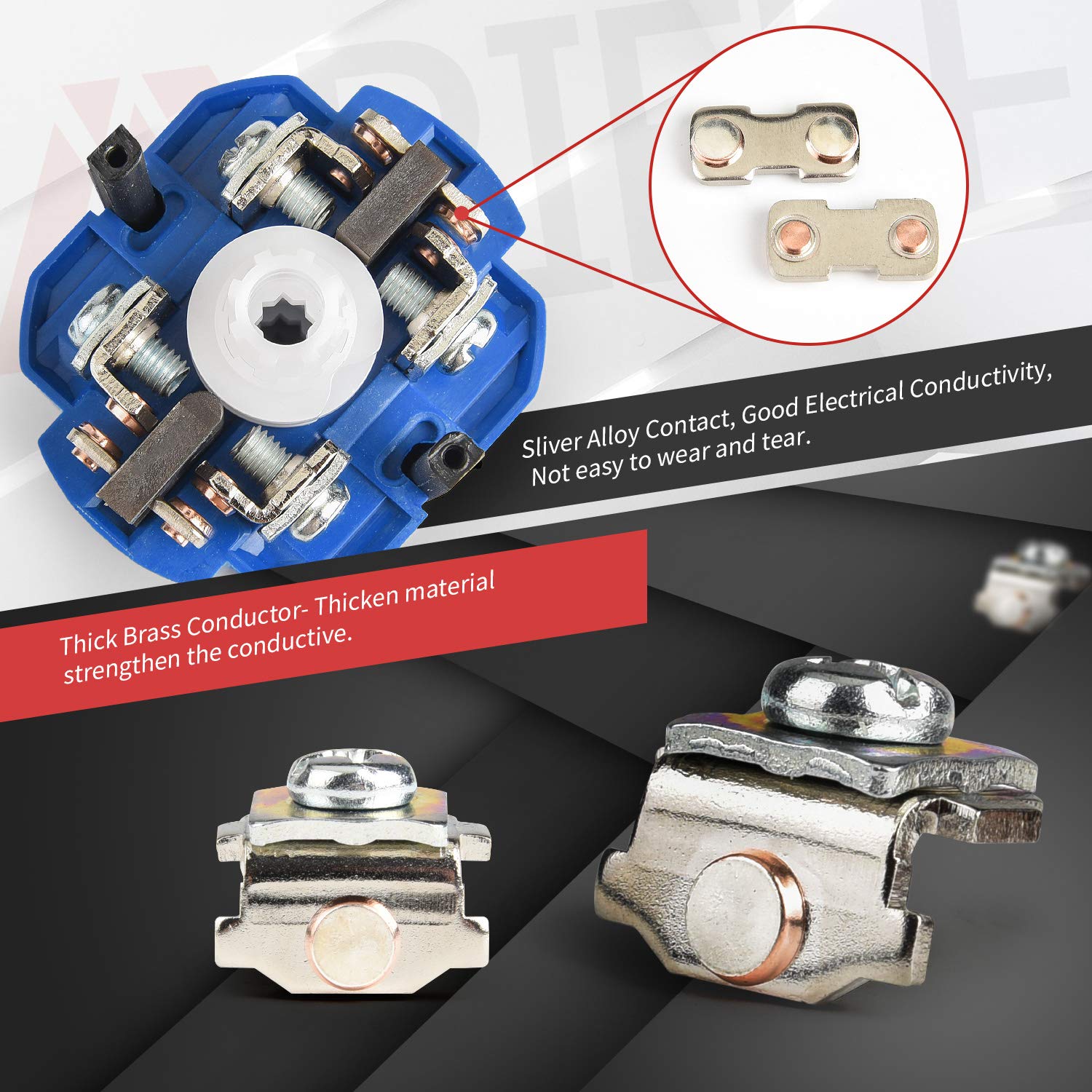
Figure 3: Internal components highlighting silver alloy contacts and thick brass conductor
4. Package Contents
The package typically includes:
- 1 x APIELE 20A 8 Terminal 3-Position Universal Rotary Changeover Selector Switch
- Mounting Screws
5. Specifications
| Specification | Value |
|---|---|
| Product Name | 3 Position Latching Selector |
| Model | LW28 (20A 8 Terminal) |
| Rated Insulation Voltage (Ui) | 690V |
| Rated Thermal Current (Ith) | 20A |
| Operating Voltage | 120V (up to 440V) |
| Number of Positions | 3 (1-0-2) |
| Number of Terminals | 8 |
| Panel Size | 48 x 48 mm |
| Installation Size | 36 x 36 mm |
| Material | Flame retardant PC, Copper, Silver Alloy |
| Protection Rating | IP20 |
| Certification | CE |
| Operation Mode | ON-NONE-ON |
| Switch Type | Rotary |
| Mounting Type | Panel Mount |
6. Installation and Wiring
6.1 Panel Mounting
The switch is designed for panel mounting. Follow these steps for installation:
- Prepare a mounting hole on your panel with dimensions of 36 x 36 mm.
- Disassemble the switch by removing the screw on the handle and detaching the front panel.
- Insert the main body of the switch through the prepared hole from the front of the panel.
- Secure the switch to the panel using the provided screws through the mounting holes.
- Reattach the front panel and handle, ensuring the screw is tightened.

Figure 4: Dimensional drawing and 8-terminal wiring diagram

Figure 5: Product Disassembly View
Video 1: Installation guide for the APIELE 3 Position 20A 8 Terminals Changeover Switch, demonstrating panel mounting and basic assembly.
6.2 Wiring Diagram
Refer to Figure 4 for the specific wiring diagram for the 8-terminal model. The switch provides three positions (1-0-2) for controlling different circuits. Ensure correct terminal connections based on your application requirements. The terminals are clearly marked for easy identification.
The table below, extracted from Figure 4, illustrates the contact closure for each position:
| Terminal | Position 1 | Position 0 | Position 2 |
|---|---|---|---|
| 1--2 | X | ||
| 3--4 | X | ||
| 5--6 | X | ||
| 7--8 | X |
Note: 'X' indicates a closed contact (connection) between the terminals in that position.
7. Operation
The APIELE Rotary Changeover Selector Switch features a simple 3-position rotary operation:
- Position 1: Rotate the handle to position '1' to activate the circuits connected to terminals 1-2 and 5-6.
- Position 0 (OFF): Rotate the handle to the center position '0' to disconnect all circuits. This is the neutral or OFF position.
- Position 2: Rotate the handle to position '2' to activate the circuits connected to terminals 3-4 and 7-8.
Ensure the handle clicks firmly into each position to ensure proper contact closure.
Video 2: Demonstration of the rotary action and position selection of the changeover switch.
8. Maintenance
The APIELE Rotary Changeover Selector Switch is designed for durability and requires minimal maintenance. However, regular checks can prolong its lifespan and ensure safe operation:
- Cleaning: Periodically clean the exterior of the switch with a dry, soft cloth. Do not use abrasive cleaners or solvents. Ensure power is off before cleaning.
- Terminal Inspection: Annually inspect terminal connections for tightness. Loose connections can lead to resistance, heat buildup, and potential failure.
- Physical Inspection: Check for any signs of physical damage, cracks, or discoloration on the switch body or handle. Replace the switch if any damage is observed.
- Operational Check: Ensure the rotary handle moves smoothly and clicks firmly into each of the three positions (1-0-2).
9. Troubleshooting
If you encounter issues with your APIELE Rotary Changeover Selector Switch, refer to the table below for common problems and solutions:
| Problem | Possible Cause | Solution |
|---|---|---|
| Switch does not activate circuit in Position 1 or 2 | Loose wiring connection; Incorrect wiring; Faulty switch contacts; No power to circuit. | Check all terminal connections for tightness. Verify wiring against the diagram (Figure 4). Test for power supply to the switch. If contacts are faulty, replace the switch. |
| Switch feels stiff or does not click into position | Internal mechanism obstruction; Wear and tear. | Do not force the handle. Inspect for external obstructions. If the issue persists, the internal mechanism may be worn; replace the switch. |
| Overheating or burning smell | Overload; Loose connections; Short circuit. | Immediately disconnect power. Check if the current draw exceeds 20A. Inspect wiring for loose connections or signs of a short circuit. Replace the switch if damaged. |
10. Warranty and Support
10.1 Warranty Information
APIELE provides a 3-year warranty for this product against manufacturing defects. If the product fails due to non-man-made broken issues within three years from the date of purchase, you are eligible for a replacement. This warranty does not cover damage caused by improper installation, misuse, unauthorized modification, or natural disasters.
10.2 Customer Support
For technical assistance, warranty claims, or any questions regarding your APIELE Rotary Changeover Selector Switch, please contact APIELE customer support through the retailer's platform or the official APIELE website. Please have your product model and purchase date available when contacting support.