
1. Introduction
This manual provides detailed instructions for the operation, maintenance, and troubleshooting of the VXSCAN NF-8209S Ethernet Cable Tester and Tracer. This device is designed for comprehensive network cable testing, including continuity, length measurement, wire tracing, Power over Ethernet (PoE) testing, and Non-Contact Voltage (NCV) detection. It is suitable for CAT5, CAT6, and CAT6a cables.

Figure 1: VXSCAN NF-8209S Ethernet Cable Tester and Tracer highlighting its multifunctional capabilities.
2. Safety Information
Please read and understand all safety warnings and operating instructions before using this product. Failure to follow these instructions may result in electric shock, fire, or serious injury.
- Do not use the device if it appears damaged.
- Do not attempt to repair or modify the device. Refer all servicing to qualified personnel.
- Ensure proper battery installation and replacement. Use only specified battery types.
- Avoid exposing the device to extreme temperatures, humidity, or direct sunlight.
- When performing NCV tests, exercise caution and assume all circuits are live until proven otherwise.
3. Package Contents
Verify that all items listed below are present in your package. If any items are missing or damaged, please contact customer support.
- 1x Emitter (Main Unit)
- 1x Receiver (Probe)
- 1x User Manual
- 1x USB Cable (Type-C)
- 1x Cable Adaptor
- 1x Carry Bag
- 1x Certification
- 2x Lithium Ion batteries (included)

Figure 2: All components included in the VXSCAN NF-8209S product package.
4. Product Overview
The VXSCAN NF-8209S consists of two main units: the Emitter (main tester) and the Receiver (probe). Familiarize yourself with the controls and ports on both units.
Emitter (Main Unit)
- LCD Screen: Displays test results and menu options.
- Power Button: Turns the device on/off.
- Navigation Buttons (Left, Enter, Right, ESC): Used for menu navigation and selection.
- RJ45 Port: For connecting network cables for testing.
- QC/CONT Port: For quality control and continuity testing.
- Flash/PoE/Length Port: For port flashing, PoE testing, and length measurement.
- RJ11 SCAN Port: For telephone line scanning.
Receiver (Probe)
- Probe: Used to detect signals from the Emitter.
- Lamp: Provides illumination in dark environments.
- Power Status Indicator: Shows battery level.
- Earphone Jack: For connecting earphones for clearer signal detection.
- Sensitivity Adjustment Knob: Adjusts the detection sensitivity (High, Middle, Low).
- SCAN Mode Button: Activates wire tracing mode.
- NCV Mode Button: Activates Non-Contact Voltage detection.
- Lamp Button: Turns the LED lamp on/off.
- Type-C Port: For charging.
- RJ45 CONT Port: For continuity testing with the Emitter.
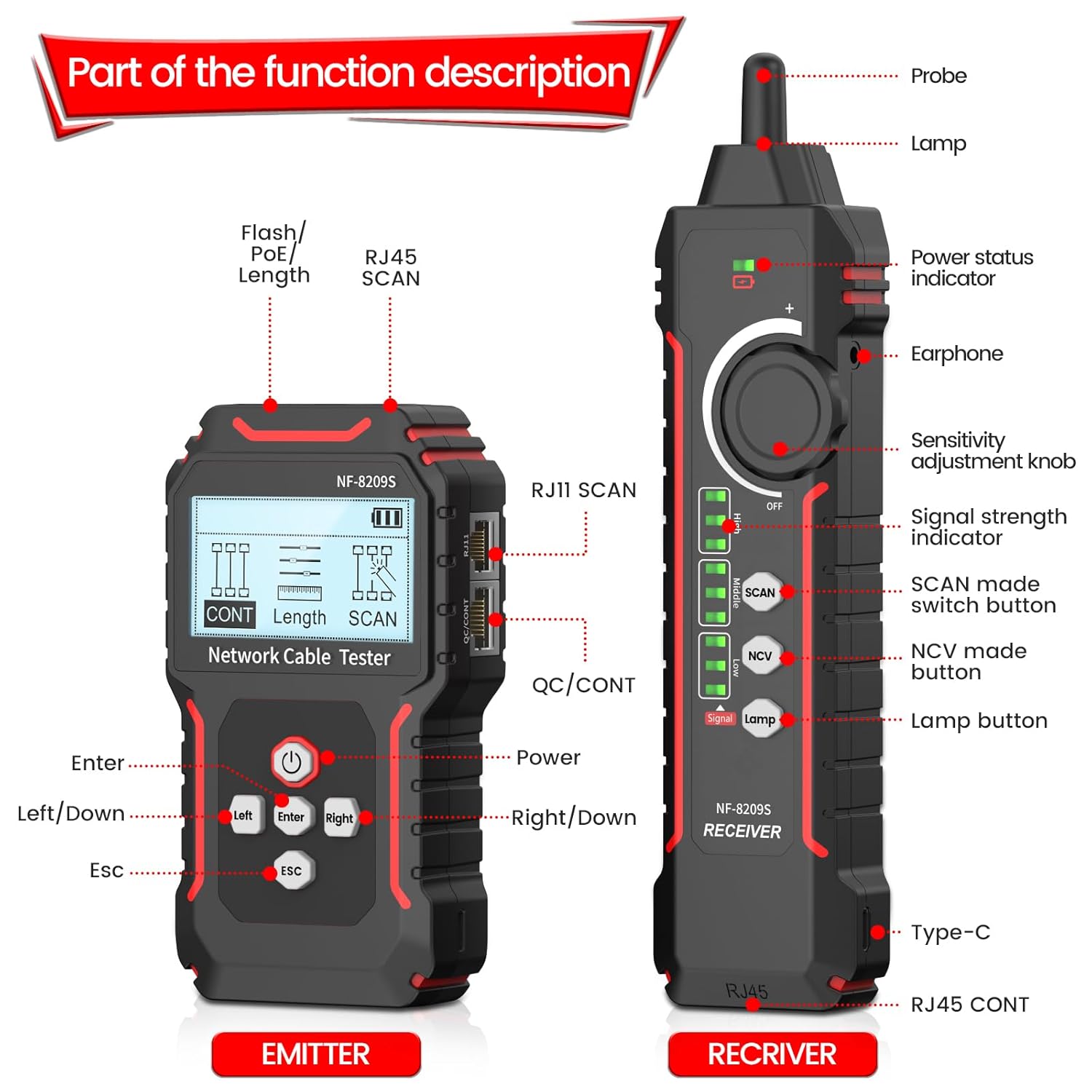
Figure 3: Labeled diagram of the Emitter and Receiver, detailing their respective components and functions.
5. Setup
Before first use, ensure the batteries are installed and charged.
5.1 Battery Installation and Charging
- The device uses 2 Lithium Ion batteries (included).
- Open the battery compartment on the Emitter and Receiver, insert the batteries according to polarity markings.
- Connect the Type-C USB cable to the Receiver's Type-C port and a suitable USB power source to charge the internal battery.
5.2 Powering On/Off
- Press and hold the Power button on the Emitter to turn it on or off.
- The Receiver typically powers on when the SCAN or NCV mode is selected via its rotary switch.
6. Operating Instructions
The NF-8209S offers multiple testing modes. Navigate through the Emitter's menu using the Left, Enter, and Right buttons.
6.1 Continuity Testing (CONT)
This mode checks for open circuits, short circuits, and crossed wires in network cables (STP, UTP).
- Connect one end of the network cable to the Emitter's RJ45 port.
- Connect the other end of the network cable to the Receiver's RJ45 CONT port.
- Select 'CONT' mode on the Emitter.
- The LCD will display the wiring status, indicating if there are open, short, or cross connections.

Figure 4: Continuity testing in progress, showing various fault indications on the Emitter's screen.
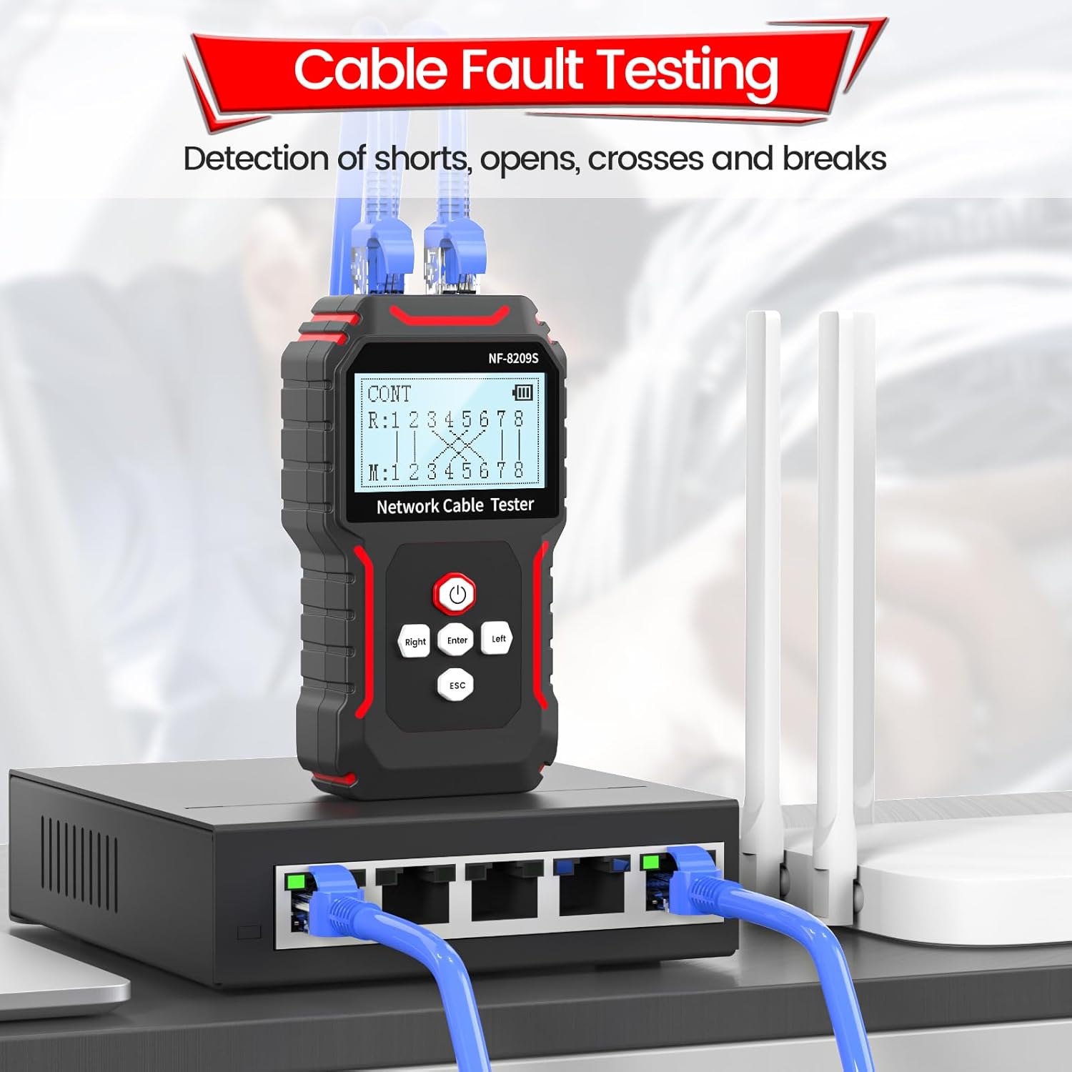
Figure 5: Cable fault testing setup, detecting shorts, opens, crosses, and breaks in network cables.
6.2 Length Measurement
This function measures the length of a network cable and identifies the distance to open or short circuits. The measurement range is 2.5m to 200m.
- Ensure the cable is disconnected from all network devices.
- Connect one end of the network cable to the Emitter's Flash/PoE/Length port.
- Select 'LENGTH' mode on the Emitter.
- The LCD will display the cable length in meters. If a fault is detected, it will show the distance to the fault.

Figure 6: Cable length measurement in progress, showing readings on the Emitter's screen.
6.3 Wire Tracing (SCAN)
The SCAN mode helps locate a specific cable among a bundle by emitting an audible tone.
- Connect one end of the network cable to the Emitter's RJ45 port.
- Select 'SCAN' mode on the Emitter.
- Turn on the Receiver and select 'SCAN' mode using its rotary switch.
- Adjust the Receiver's sensitivity knob.
- Move the Receiver's probe along the cables. The loudest tone indicates the target cable.
6.4 PoE Testing
This mode tests standard PoE equipment, identifying af/at standards, power supply voltage, polarity, and mode.
- Connect the network cable from the PoE source to the Emitter's Flash/PoE/Length port.
- Select 'POE' mode on the Emitter.
- The LCD will display PoE information such as standard (af/at), voltage, and power supply mode.

Figure 7: PoE testing in action, showing the device connected to a PoE camera and displaying power information.
6.5 Port Flashing (FLASH)
This feature helps locate a network port on a hub or switch by making its indicator light flash.
- Connect the network cable to the Emitter's Flash/PoE/Length port and the other end to a port on the hub/switch.
- Select 'FLASH' mode on the Emitter.
- Observe the indicator lights on the hub/switch; the connected port's light will flash, identifying it.
6.6 NCV Test (Non-Contact Voltage)
The Receiver can detect the presence of AC voltage (50V-1000V) without direct contact.
- Turn on the Receiver and select 'NCV' mode using its rotary switch.
- Bring the tip of the Receiver's probe close to an AC voltage source (e.g., an electrical outlet or live wire).
- The Receiver will indicate the presence of voltage through an audible alert and/or visual indicator.
7. Maintenance
Proper maintenance ensures the longevity and accuracy of your device.
- Cleaning: Use a soft, dry cloth to clean the device. Do not use abrasive cleaners or solvents.
- Storage: Store the device in its carry bag in a cool, dry place away from direct sunlight and extreme temperatures.
- Battery Care: If the device will not be used for an extended period, remove the batteries to prevent leakage. Recharge batteries regularly if they are rechargeable.
- Calibration: The device is factory calibrated. If you suspect inaccuracies, contact customer support for service.
8. Troubleshooting
Refer to the following table for common issues and their solutions.
| Problem | Possible Cause | Solution |
|---|---|---|
| Device does not power on. | Low or dead batteries; incorrect battery installation. | Replace or recharge batteries; ensure correct polarity. |
| Inaccurate length measurement. | Cable connected to network device; cable length outside range (2.5m-200m). | Disconnect cable from all devices; ensure cable is within specified length range. |
| No signal detected during SCAN. | Receiver sensitivity too low; Emitter not in SCAN mode; cable not properly connected. | Increase Receiver sensitivity; ensure Emitter is in SCAN mode; check cable connections. |
| Continuity test shows incorrect results. | Poor cable connection; damaged cable. | Ensure cables are securely connected; inspect cable for visible damage. |
9. Specifications
- Model: NF-8209S
- Brand: VXSCAN
- Power Source: Battery Powered (2 Lithium Ion batteries included)
- Cable Types: CAT5, CAT6, CAT6a (RJ45)
- Length Measurement Range: 2.5m - 200m
- NCV Detection: 50V - 1000V AC
- PoE Test: Supports af/at standards, voltage, polarity, mode
- Dimensions: 27.2 x 16.69 x 4.39 cm (Parcel Dimensions)
- Weight: 549 g
- Certifications: CE, RoHS
10. Warranty and Support
The VXSCAN NF-8209S comes with a standard manufacturer's warranty. For specific warranty terms and conditions, please refer to the warranty card included in your package or contact VXSCAN customer support.
For technical assistance, troubleshooting, or service inquiries, please visit the official VXSCAN website or contact their customer service department. Contact information can typically be found on the product packaging or the manufacturer's website.