1. Introduction
This manual provides detailed instructions for the safe and efficient operation of your Aideepen PWM DC Motor Speed Controller. Please read this manual thoroughly before installation and use, and retain it for future reference. This device is designed for precise control of DC motor speeds within a 6V-60V range, offering stable performance and a wide range of applications.
2. Product Features
- Durability and Stability: Constructed from durable PCB material, ensuring stable product performance and a long operational lifespan. Features a digital encoder knob for high precision control.
- High Performance: Supports an input voltage range of DC 6V-60V. Provides a maximum output current of 30A, with a continuous output current of 20A. The duty cycle is continuously adjustable from 0% to 100%.
- User-Friendly Installation: Designed with a grid terminal block and a button interface for ease of use. Allows for setting slow start and stop times, limiting upper and lower speed thresholds, and adjusting the control frequency from 1-100KHz.
- Versatile Applications: Ideal for controlling the speed of various DC-powered devices, including DC motors, fans, aquarium oxygen pumps, and other products operating within the 6V-60V DC range.
3. Package Contents
Upon opening the package, please verify that all items are present and undamaged:
- 1x Aideepen PWM DC Motor Speed Controller (Model: BLM-30A)
- 1x Instruction Manual
4. Specifications
| Parameter | Value |
|---|---|
| Product Dimensions | 9.6 x 6.1 x 3.4 cm |
| Weight | 100 grams |
| Input Voltage Range | DC 6V-60V |
| Output Voltage | Linear load |
| Maximum Output Current | 30A |
| Continuous Output Current | 20A |
| Speed Adjustment Range | 0% to 100% |
| Adjustment Method | Potentiometer (Digital Encoder Knob) |
| Control Type | Current control |
| Control Frequency | 15KHz (Adjustable 1-100KHz) |
| Wiring Type | Screw Terminal |
Note: Specifications are subject to change without prior notice.
5. Safety Information
Please read and adhere to the following safety warnings to prevent damage to the device or personal injury:
- Input Voltage: The input voltage must be DC 6V-60V. It is crucial to distinguish between the positive and negative poles.
- DO NOT Input 220V AC: Connecting 220V AC power will severely damage the controller and may pose a safety hazard.
- Voltage Matching: The input voltage supplied to the controller should match the rated voltage of the DC motor being controlled (within the 6V-60V range).
- Polarity: Always ensure correct polarity when connecting power and motor leads. Incorrect wiring can cause malfunction or damage.
- Environment: Operate the controller in a dry, well-ventilated area, away from flammable materials, moisture, and extreme temperatures.
- Professional Installation: If you are unsure about wiring or installation, seek assistance from a qualified electrician or technician.
6. Setup and Installation
Follow these steps for proper installation of the motor speed controller:
- Prepare Wiring: Ensure all power is disconnected before making any connections. Prepare appropriate gauge wires for your power supply and DC motor.
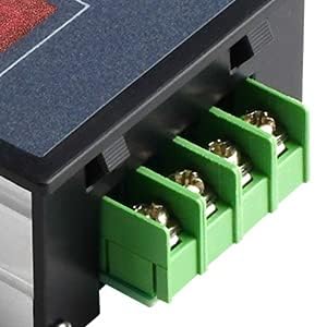
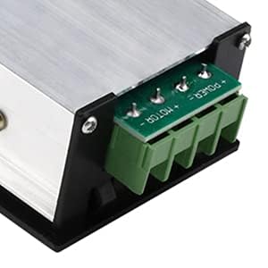
- Identify Terminals: The controller features screw terminals for connections. There are two sets of terminals: one for power input and one for motor output.
- Connect Power Input: Connect your DC 6V-60V power supply to the input terminals. The terminal labeled 'POWER +' is for the positive lead, and 'POWER -' is for the negative lead. Observe polarity carefully.
- Connect Motor Output: Connect your DC motor to the output terminals. The terminal labeled 'MOTOR +' is for the positive lead of the motor, and 'MOTOR -' is for the negative lead.

7. Operating Instructions
The Aideepen PWM DC Motor Speed Controller features a digital display, a rotary encoder knob, and a 'SET' button for operation.

7.1 Basic Operation
- Power On: Once wired correctly, apply DC power (6V-60V). The digital display will illuminate, showing the current speed percentage or a parameter.
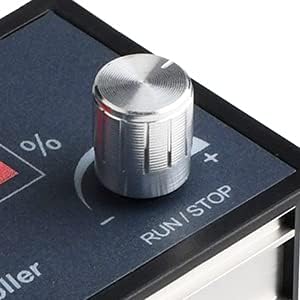
- Start/Stop Motor: A short press of the rotary encoder knob (labeled RUN/STOP) will start or stop the connected DC motor.
- Adjust Speed: Rotate the rotary encoder knob clockwise to increase the motor speed and counter-clockwise to decrease it. The digital display will show the current speed as a percentage (0-100%).
7.2 Advanced Settings (Parameter Mode)
The controller allows for advanced configuration of various parameters:
- Enter Setting Mode: A long press of the rotary encoder knob (RUN/STOP) will enter the setting mode. The display will show a parameter code (e.g., P-1, P-2).
- Navigate Parameters: Rotate the knob to cycle through different parameter codes.
- Select Parameter: Short press the 'SET' button to select the currently displayed parameter for adjustment.
- Adjust Parameter Value: Rotate the knob to change the value of the selected parameter.
- Confirm Value: Short press the 'SET' button again to confirm the new value and move to the next parameter or exit the current parameter setting.
- Exit Setting Mode: Long press the rotary encoder knob again to exit the setting mode and return to normal operation.
Commonly Adjustable Parameters:
- Slow Start Time: Configures the time it takes for the motor to reach full speed from a stop.
- Slow Stop Time: Configures the time it takes for the motor to come to a complete stop from full speed.
- Upper Speed Limit: Sets the maximum achievable speed percentage.
- Lower Speed Limit: Sets the minimum operational speed percentage.
- Control Frequency: Adjusts the PWM frequency (1-100KHz) for compatibility with different motors.
8. Maintenance
To ensure the longevity and optimal performance of your Aideepen PWM DC Motor Speed Controller, follow these maintenance guidelines:
- Keep Clean: Regularly clean the exterior of the controller with a soft, dry cloth. Avoid using harsh chemicals or abrasive materials.
- Avoid Moisture: Protect the device from water, humidity, and other liquids. Moisture can cause short circuits and damage internal components.
- Check Connections: Periodically inspect all wiring connections to ensure they are secure and free from corrosion. Loose connections can lead to intermittent operation or overheating.
- Ventilation: Ensure the controller has adequate ventilation to prevent overheating, especially during prolonged operation at high loads.
- Storage: When not in use for extended periods, store the controller in a cool, dry place.
9. Troubleshooting
If you encounter issues with your motor speed controller, refer to the following troubleshooting guide:
| Problem | Possible Cause | Solution |
|---|---|---|
| Controller does not power on / Display is off | No power input; Incorrect input voltage; Incorrect polarity; Loose connection. | Check power supply (6V-60V DC). Verify input voltage and ensure correct positive/negative polarity. Secure all power connections. |
| Motor does not run | Motor not connected; Incorrect motor polarity; Motor damaged; Controller in 'STOP' mode; Speed set to 0%. | Check motor connections and polarity. Ensure motor is functional. Short press RUN/STOP knob to start. Increase speed using the knob. |
| Motor runs at incorrect speed / Speed cannot be adjusted | Speed limits set too low/high; Potentiometer malfunction; Incorrect control frequency. | Enter setting mode (long press RUN/STOP) and check upper/lower speed limits. Verify control frequency (1-100KHz) is suitable for your motor. |
| Motor runs erratically / Overheats | Overload; Poor ventilation; Loose connections; Incompatible motor. | Reduce motor load. Ensure adequate ventilation around the controller. Check all wiring connections. Confirm motor is compatible with PWM control and voltage/current ratings. |
| Display shows error code | Internal fault; Overcurrent/Overvoltage protection triggered. | Disconnect power, wait a few minutes, then reconnect. If the error persists, contact customer support. |
10. Warranty and Support
Aideepen products are manufactured to high-quality standards. For specific warranty information, return policies, or technical support, please refer to the documentation provided at the time of purchase or contact Aideepen customer service directly through their official channels. Please have your product model number (BLM-30A) and purchase details ready when contacting support.
For additional resources and product information, you may visit the Aideepen store on Amazon or their official website.


