
1. Introduction
This manual provides detailed instructions for the Hosyond 2.8-inch ESP32 Display Resistive Touch Screen module. This module integrates an ESP32-WROOM-32 microcontroller with a 2.8-inch TFT LCD, offering WiFi and Bluetooth connectivity, a resistive touch interface, and an ILI9341 driver. It is designed for various embedded projects, including those based on Arduino, Raspberry Pi, and other microcontrollers.
The module features a 240x320 resolution display with 16-bit RGB 65K color support, a TF card slot for expanded storage, and multiple expansion interfaces for enhanced functionality. This guide will assist you with setup, operation, maintenance, and troubleshooting to ensure optimal use of your display module.
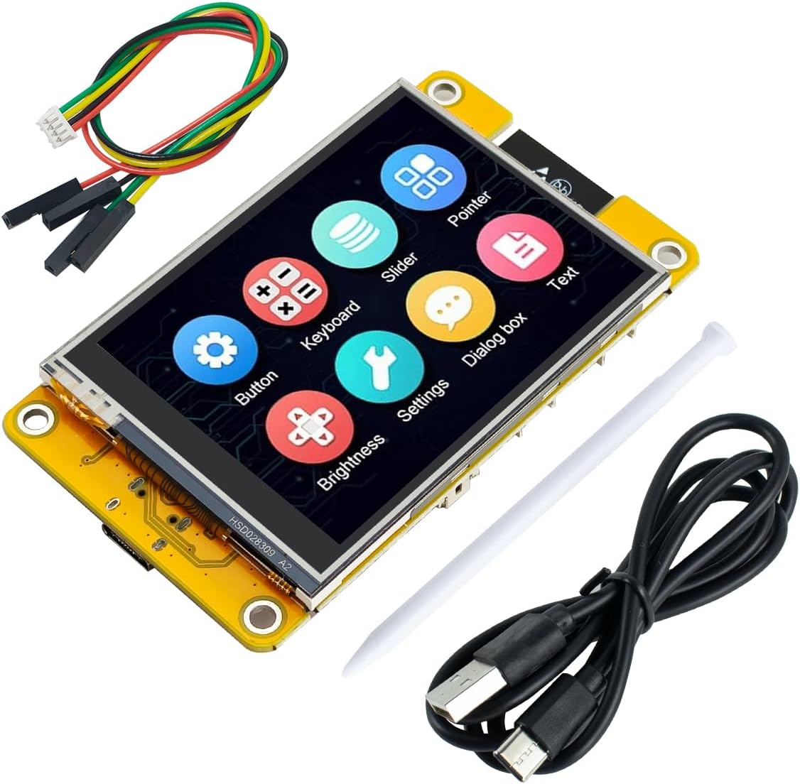
Figure 1: Front view of the Hosyond 2.8-inch ESP32 Display Resistive Touch Screen module.
2. Key Features
- Controller: Integrates ESP32-WROOM-32 module with dual-core MCU, Wi-Fi, and Bluetooth. Features a main frequency up to 240MHz, 520KB SRAM, 448KB ROM, and 4MB flash memory.
- Display: 2.8-inch LCD color screen with 240x320 resolution, supporting 16-bit RGB 65K color display.
- Touch Screen: Resistive touch function for interactive control.
- Multi-functionality: Includes LCD display, backlight control, touch screen control, speaker drive, photosensitive circuit, and RGB-LED control circuits.
- Expansion Interfaces: Equipped with TF card interface, serial port interface, temperature and humidity sensor interface (DHT11), and reserved IO interfaces.
- Development Support: Compatible with Arduino library functions and sample programs. Supports one-click program download and development with Arduino IDE, ESP IDE, Micropython, and Mixly.
- Pre-programmed: The module comes pre-programmed from the factory, allowing for immediate use upon connection.
- Durability: Designed to military-grade process standards for long-term stable operation.

Figure 2: Visual representation of the module's key features.
3. Package Contents
Verify that all components listed below are included in your package:
- 1 x 2.8'' ESP32 Display Module
- 1 x USB Cable (Type-A to Type-C)
- 1 x Touch Pen (Color may vary: pink, white, black, or green)
- 1 x 4-Pin Connector Cable
- 1 x Packaging box for display

Figure 3: Contents of the Hosyond 2.8-inch ESP32 Display module package.
4. Board Layout and Pinout
Understanding the board layout is crucial for proper connection and development. Refer to the diagram below for key components and interfaces.

Figure 4: Back view of the module with labeled components including RESET Key, Speaker Interface, SPI Peripheral Interface, Expand Pin, ESP32-32E Module, MicroSD Card Slot, Serial Port, Battery Interface, BOOT Key, and Type-C Port.
4.1 Key Interfaces:
- Type-C Port: Used for power supply and data communication (programming).
- RESET Key: Resets the ESP32 module.
- BOOT Key: Used for entering bootloader mode for flashing firmware.
- Speaker Interface: For connecting an external speaker.
- SPI Peripheral Interface: For connecting other SPI devices.
- Expand Pin: General Purpose Input/Output (GPIO) pins for additional connections.
- MicroSD Card Slot: For expanding storage, useful for storing images, data logs, or firmware.
- Serial Port: For serial communication.
- Battery Interface: For connecting a LiPo battery (JST 1.25mm pitch connector).
- RGB LED: Programmable multi-color LED.
5. Setup Guide
5.1 Initial Connection
- Connect the provided USB-C cable to the Type-C port on the ESP32 display module.
- Connect the other end of the USB cable to your computer's USB port. The display should power on and show a pre-installed demo program.
- If using a battery, connect it to the Battery Interface. Ensure correct polarity.
5.2 Software Environment Setup (Arduino IDE Example)
To develop custom applications, you will need to set up your development environment. The following steps outline the process for Arduino IDE:
- Install Arduino IDE: Download and install the latest version of the Arduino IDE from the official Arduino website.
- Add ESP32 Board Manager URL:
- Go to File > Preferences.
- In the "Additional Board Manager URLs" field, add:
https://raw.githubusercontent.com/espressif/arduino-esp32/gh-pages/package_esp32_index.json - Click OK.
- Install ESP32 Boards:
- Go to Tools > Board > Board Manager...
- Search for "ESP32" and install the "esp32 by Espressif Systems" package.
- Install Required Libraries:
- This module uses the ILI9341 driver for the display and XPT2046 for the resistive touch screen. You will need to install compatible libraries. A common choice is the TFT_eSPI library.
- Go to Sketch > Include Library > Manage Libraries...
- Search for "TFT_eSPI" and install it.
- After installing TFT_eSPI, you will need to configure its
User_Setup.hfile to match the specific pinout and driver of this Hosyond module. Refer to the official Hosyond website for detailed pin assignments and recommended configurations.
- Select Board and Port:
- Go to Tools > Board and select the appropriate ESP32 board (e.g., "ESP32 Dev Module").
- Go to Tools > Port and select the serial port connected to your ESP32 module.
For detailed tutorials, sample programs, and specific library configurations, visit the official Hosyond website. This resource provides comprehensive documentation to facilitate rapid secondary development.
Video 1: An overview of the 2.8'' ESP32 Display Resistive Touchscreen module, demonstrating its features and basic operation. This video is provided by the seller, HONGXINBAORUI.
6. Operating Instructions
6.1 Basic Display Operation
Once powered, the module will execute the loaded firmware. If no custom firmware is loaded, it will run the factory-installed demo. The 2.8-inch TFT LCD provides a 240x320 resolution display with 16-bit color depth.

Figure 5: Example of graphical output on the 2.8-inch ESP32 Display module.
6.2 Resistive Touch Screen Usage
The module features a resistive touch screen. This technology requires a slight pressure to register input, unlike capacitive screens found on smartphones. Use the included stylus or a fingernail for best results. Avoid using sharp objects that could damage the screen surface.
6.3 TF Card Functionality
The integrated TF card slot allows for expanded storage. This can be used to store:
- Graphical assets for your user interface.
- Data logs from sensors connected to the ESP32.
- Configuration files for your applications.
Ensure the TF card is formatted correctly (typically FAT32) before use. Refer to your programming environment's documentation for specific TF card library usage.
6.4 Wi-Fi and Bluetooth Connectivity
The ESP32-WROOM-32 module provides integrated 2.4GHz Wi-Fi (802.11b/g/n) and Bluetooth (V4.2 BR/EDR and LE standards). These wireless capabilities enable the module to connect to networks, communicate with other devices, and implement IoT functionalities.

Figure 6: The module's wireless connectivity allows interaction with phones, pads, routers, and computers.
Programming for Wi-Fi and Bluetooth typically involves using the respective libraries provided by the ESP32 Arduino core or ESP-IDF. Consult Espressif's documentation for detailed API references.
7. Maintenance
- Cleaning: Use a soft, dry cloth to clean the display and module. Avoid abrasive cleaners or solvents. For the screen, a slightly damp, lint-free cloth can be used, but ensure no liquid enters the module.
- Storage: Store the module in a dry, anti-static environment, away from direct sunlight and extreme temperatures. The provided packaging box is suitable for storage.
- Handling: Handle the module by its edges to avoid touching sensitive electronic components. Static electricity can damage the board, so use anti-static precautions when handling.
- Firmware Updates: Regularly check the Hosyond website or relevant community forums for firmware updates or improved libraries that may enhance performance or add new features.
8. Troubleshooting
8.1 Display Not Lighting Up
- Power Check: Ensure the USB-C cable is securely connected to both the module and a power source (computer or USB adapter).
- Cable Integrity: Try a different USB-C cable to rule out a faulty cable.
- Driver Installation: If attempting to run custom code, verify that the display driver (ILI9341) is correctly initialized in your code and that the backlight pin is configured and enabled.
8.2 Touch Screen Unresponsive or Inaccurate
- Stylus Use: Ensure you are using the included stylus or a similar non-sharp object, applying slight pressure. Resistive touch screens require physical contact and pressure.
- Calibration: Resistive touch screens often require calibration. If your custom code does not include calibration, implement one. Refer to the Hosyond website or community resources for calibration examples.
- Library Configuration: Verify that the XPT2046 touch controller library is correctly installed and configured with the correct SPI pins in your
User_Setup.hfile (for TFT_eSPI).
8.3 Uploading Code Fails
- Port Selection: Double-check that the correct serial port is selected in your IDE (e.g., Arduino IDE: Tools > Port).
- Board Selection: Ensure the correct ESP32 board is selected (e.g., "ESP32 Dev Module").
- Boot Mode: Sometimes, you may need to manually put the ESP32 into bootloader mode. Hold down the BOOT button, press and release the RESET button, then release the BOOT button. Then attempt to upload.
- Driver Issues: On some operating systems, USB-to-serial drivers (e.g., CH340) might be required. Ensure they are installed.
8.4 Wi-Fi/Bluetooth Connectivity Issues
- Code Verification: Ensure your Wi-Fi or Bluetooth code is correct, including SSID, password, and connection logic.
- Antenna: The ESP32 module has an integrated antenna. Ensure there are no obstructions or metallic enclosures interfering with the signal.
- Power Supply: Insufficient power can sometimes affect wireless performance. Ensure a stable 5V power supply.
9. Technical Specifications
| Parameter | Value |
|---|---|
| Display Color | RGB 65K color |
| Size | 2.8 inch |
| Display Type | TFT |
| Driver Chip | ILI9341 |
| Resolution | 240x320 (Pixel) |
| Effective Display Area | 43.2 x 57.6 mm |
| Module Size | 50.0 x 86.0 mm |
| View Angle | >60° |
| Operating Temperature | -20℃ ~ 70℃ |
| Storage Temperature | -30℃ ~ 80℃ |
| Operating Voltage | 5V |
| Power Consumption | About 115mA |
| Module | ESP32-32E |
| CPU | ESP32-D0WD-V3, Xtensa dual-core 32-bit LX6 microprocessor |
| Frequency | 240MHz (Max) |
| Memory | 48KB ROM + 520KB SRAM + 16KB RTC SRAM + 4MB external QSPI Flash |
| Wi-Fi | 2.4GHz and 802.11b/g/n modes |
| Bluetooth | BT V4.2 BR/EDR and BT LE standards |
| Processor Count | 2 |
| Connectivity Technology | Bluetooth, Wi-Fi |
| Compatible Devices | Arduino boards, Raspberry Pi, ESP, Mixly, Computers, Game Consoles, Microcontrollers |
10. Warranty Information
This product is provided without an explicit warranty. For specific return or replacement policies, please refer to the retailer's terms and conditions at the time of purchase.
11. Customer Support
For further assistance, detailed documentation, and community support, please visit the official Hosyond website. You can also refer to the product page on Amazon for additional resources and customer reviews that may offer helpful tips and solutions.
- Hosyond Website: www.hosyond.com (Note: This is a placeholder URL, please verify the actual support website from the product packaging or official sources.)
- Amazon Product Page: https://www.amazon.com/dp/B0D92C9MMH