
1. Introduction
This manual provides comprehensive instructions for the installation, operation, and maintenance of the GODIYMODULES 500W 1:1 Waterproof HF Balun. This device is designed to facilitate efficient impedance matching for various HF antenna configurations, including inverted V and shortwave antennas, across the 160m to 6m bands (1.8-50MHz). Please read this manual thoroughly before use to ensure proper and safe operation.

Figure 1: Side view of the GODIYMODULES 500W 1:1 Waterproof HF Balun, showing the eye bolt for mounting and one of the wing nut terminals.
2. Safety Information
Always observe the following safety precautions to prevent injury or damage to the equipment:
- High Voltage: Antennas can carry high voltages. Ensure all power to transmitting equipment is off before connecting or disconnecting the balun.
- Mounting: Securely mount the balun to prevent it from falling, especially in windy conditions. Use appropriate hardware for the mounting location.
- Weather Protection: While the balun is waterproof, ensure all connections (especially the coaxial cable) are properly sealed and protected from moisture to prevent signal loss and corrosion.
- Lightning: Disconnect the antenna from your radio equipment during lightning storms to prevent damage.
- Power Rating: Do not exceed the specified 500W power rating to avoid damage to the balun.
3. Package Contents
Verify that all items are present in the package:
- 1 x GODIYMODULES 500W 1:1 Waterproof HF Balun
- (Additional mounting hardware or instructions may be included depending on the specific kit)
4. Product Overview and Features
The GODIYMODULES 500W 1:1 Waterproof HF Balun is a robust device designed for amateur radio and shortwave listening applications. It provides a 1:1 voltage transformation ratio, effectively converting balanced antenna impedances to unbalanced coaxial cable impedances, and vice-versa.
Key Features:
- Power Rating: Handles up to 500 Watts.
- Frequency Range: Operates across 1.8 MHz to 50 MHz (160m to 6m bands).
- Impedance Ratio: 1:1 Voltage Balun.
- Connector Type: Standard SO-239 for coaxial cable connection.
- Antenna Connections: Two wing nut terminals for balanced antenna elements.
- Waterproof Design: Constructed for outdoor use in various weather conditions.
- Durable Construction: Made from high-quality materials for long service life.
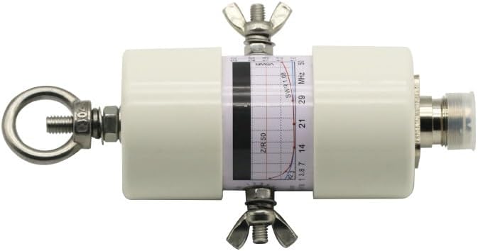
Figure 2: Front view of the balun, highlighting the SWR performance graph and connection points.
5. Setup and Installation
Follow these steps to properly install your HF Balun:
- Mounting Location: Select a suitable location for your antenna, typically at the feed point of a dipole, inverted V, or other balanced antenna. Ensure the location provides adequate support and clearance from obstructions.
- Secure Mounting: Use the integrated eye bolt (Figure 1) to suspend the balun. Ensure the mounting point is strong enough to support the balun and the antenna wires, especially under wind load. Use a durable rope or non-conductive support.
- Antenna Wire Connection: Connect the two elements of your balanced antenna to the wing nut terminals on the balun (Figure 2). Ensure a secure electrical connection. For optimal performance, use appropriate gauge wire for your antenna.
- Coaxial Cable Connection: Connect your 50 Ohm coaxial cable (e.g., RG-8X, RG-213) to the SO-239 connector on the bottom of the balun (Figure 3). Ensure the connector is tightened securely.
- Weatherproofing Connections: Although the balun itself is waterproof, it is highly recommended to weatherproof the coaxial cable connection using self-amalgamating tape or a suitable weather-sealing compound to prevent moisture ingress into the connector.
- Cable Routing: Route the coaxial cable away from the antenna elements at a 90-degree angle for at least a quarter wavelength to minimize common mode currents.
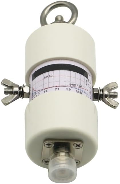
Figure 3: Bottom view of the balun, showing the SO-239 connector for coaxial cable attachment.
6. Operating Instructions
Once the balun and antenna are properly installed, you can begin operation.
- Connect to Transceiver: Connect the other end of your coaxial cable to your radio transceiver's antenna port.
- SWR Measurement: Before transmitting, always check the Standing Wave Ratio (SWR) using an SWR meter or the built-in SWR meter of your transceiver. The balun is designed to provide a 1:1 impedance ratio, but the overall SWR will depend on the antenna's tuning and environment.
- Frequency Range: The balun is effective across the 1.8 MHz to 50 MHz range. Ensure your antenna is also tuned for your desired operating frequency within this range.
- Power Output: Do not exceed the 500W power rating of the balun. Operating above this limit can cause damage to the balun and potentially your transceiver.
- Antenna Tuning: If your SWR is high, adjust your antenna's length or configuration as needed. The balun's function is to transform impedance, not to tune the antenna itself.
7. Maintenance
Regular maintenance ensures the longevity and optimal performance of your balun.
- Visual Inspection: Periodically inspect the balun and its connections for any signs of physical damage, corrosion, or wear, especially after severe weather.
- Connection Integrity: Check that all antenna wire connections and the coaxial cable connection remain tight and secure.
- Waterproofing: Re-inspect the weatherproofing of the coaxial connector annually or as needed. Reapply weather-sealing tape if it shows signs of degradation.
- Cleaning: If necessary, gently clean the exterior of the balun with a damp cloth. Avoid using harsh chemicals or abrasive materials.
8. Troubleshooting
If you encounter issues, consider the following common troubleshooting steps:
- High SWR:
- Check antenna wire connections to the balun for looseness or corrosion.
- Verify the coaxial cable connection to the balun and transceiver is secure.
- Ensure the antenna itself is properly tuned for the operating frequency. The balun does not tune the antenna.
- Inspect the coaxial cable for damage.
- No Signal/Poor Reception:
- Confirm all connections are secure.
- Check if the antenna is properly mounted and not shorted.
- Test the coaxial cable for continuity.
- Ensure your transceiver settings are correct for the band and mode.
- Intermittent Operation:
- Look for loose connections or damaged wiring that might be affected by wind or movement.
- Inspect for signs of water ingress into connectors.
9. Specifications
| Feature | Specification |
|---|---|
| Model | 500W 1:1 HF Balun |
| Brand | GODIYMODULES |
| Power Rating | 500W |
| Frequency Band | 1.8 - 50 MHz (160m - 6m) |
| Impedance Ratio | 1:1 Voltage |
| Input Connector | SO-239 |
| Output Connections | Wing Nut Terminals |
| Impedance | 50 Ohms |
| Maximum Range | 160 Meters (referring to 160m band operation) |
| Product Dimensions (L x W x H) | 88"L x 45"W x 140"H |
| Manufacturer | GODIYMODULES |
| Color | White |
Note: The provided product dimensions (88"L x 45"W x 140"H) appear to be for a larger antenna system rather than the compact balun unit itself. Please refer to the product packaging or manufacturer's website for precise balun dimensions.
10. Warranty Information
This GODIYMODULES 500W 1:1 Waterproof HF Balun is covered by a 2-Year Manufacturer Warranty from the date of purchase. This warranty covers defects in materials and workmanship under normal use. It does not cover damage caused by misuse, accident, unauthorized modification, or exceeding the specified power rating.
For warranty claims or service, please retain your proof of purchase and contact the manufacturer or authorized reseller.
11. Customer Support
If you have any questions, require technical assistance, or need further support regarding your GODIYMODULES 500W 1:1 Waterproof HF Balun, please contact your retailer or the manufacturer directly. Refer to the product packaging or the manufacturer's official website for contact details.