1. Introduction
This manual provides essential information for the safe and effective installation, operation, and maintenance of your Hilitand Automatic Transfer Switch (ATS) model CHLT-GX2. This device is designed to automatically switch power sources between a main supply and a backup supply, such as a generator or inverter, ensuring continuous power for critical loads. Please read this manual thoroughly before installation and use, and retain it for future reference.
2. Safety Information
WARNING: Electrical shock hazard. Installation and servicing must be performed by qualified personnel only. Failure to follow these instructions may result in serious injury or death.
- Always disconnect all power sources before installing or servicing the ATS.
- Ensure all wiring complies with local and national electrical codes.
- Verify correct voltage and current ratings before connecting the device.
- Do not operate the ATS if it is damaged or appears to be malfunctioning.
- The device is designed for indoor use in environments meeting specified temperature and humidity ranges.
3. Product Overview
The Hilitand CHLT-GX2 is an automatic transfer switch designed for power system stability. It features a flame-retardant PC material construction for enhanced safety.
Key Features:
- Smooth Power Transfer: Automatically switches load from main power to standby during outages or voltage fluctuations, ensuring uninterrupted power supply with L1>L2>L3 priority.
- Versatile Power Prioritization: Prioritize mains power, generator, and inverter with adjustable voltage thresholds for under/over voltage switching.
- Premium Safety Features: Constructed from high fireproof PC material, offering sensitive operation, accurate measurement, and minimal heat generation.
- Customizable Parameters: Adjust transfer time, reset time, over/under voltage, and overcurrent settings for tailored operation.
- Wide Application: Suitable for commercial buildings, medical facilities, data centers, and communication base stations requiring continuous and stable power supply.
Components and Display:
The device features a digital display for voltage and current, along with control buttons for setting parameters.

Figure 3.1: System diagram illustrating the 3-way automatic transfer switch connecting to public power, an inverter, and a generator.

Figure 3.2: Icons depicting the main functionalities: Voltage display, Current display, Convenient connection, Three groups of switching voltages, Rail mounting, and Status indication.
4. Specifications
| Parameter | Value |
|---|---|
| Model | CHLT-GX2 |
| Material | Flame retardant PC |
| Power Terminals | N, L1, L2, L3 |
| Auto Reclosing Delay (Ton) | 1-600s |
| Return Priority Stage Delay | 1-600s |
| Switch Delay To Reserve Phase | Voltage Hysteresis: 5V |
| Overvoltage Trip Delay | 0.1s; ≥350V: 0.02s |
| Undervoltage Trip Delay | 0.1s; ≥350V: 0.02s |
| Voltage Accuracy | Maximum Operating Phase Voltage: 350V |
| Rated Operating Current | 63A |
| Maximum Operating Current | 80A |
| Pollution Degree | 3 |
| Altitude | ≤2000m |
| Operating Temperature | -25℃~+50℃ |
| Relative Humidity | ≤50% at 40℃ (non condensing) |
| Wire Size | 0.5mm²-1mm² |
| Installation | 35mm standard mounting rail |
| Package Dimensions | 4.33 x 3.94 x 3.15 inches |
| Item Weight | 13.7 ounces |

Figure 4.1: Dimensions of the Hilitand Automatic Transfer Switch.
5. Installation
IMPORTANT: Ensure all power is disconnected before proceeding with installation.
5.1 Mounting
- The CHLT-GX2 is designed for installation on a standard 35mm DIN rail.
- Securely attach the device to the DIN rail in an appropriate electrical enclosure, ensuring adequate ventilation and clearance.
5.2 Wiring
Connect the power sources and load to the designated terminals as shown in the wiring diagram. Use appropriate wire sizes (0.5mm²-1mm²) for all connections.
- Input Terminals (IN): Connect the main power supply (e.g., public grid, generator, inverter) to the N, L1, L2, L3 terminals. The device supports three-phase input.
- Output Terminals (Output): Connect the load to the N and L terminals on the output side.
- Ensure all connections are tight and secure to prevent loose contacts and overheating.
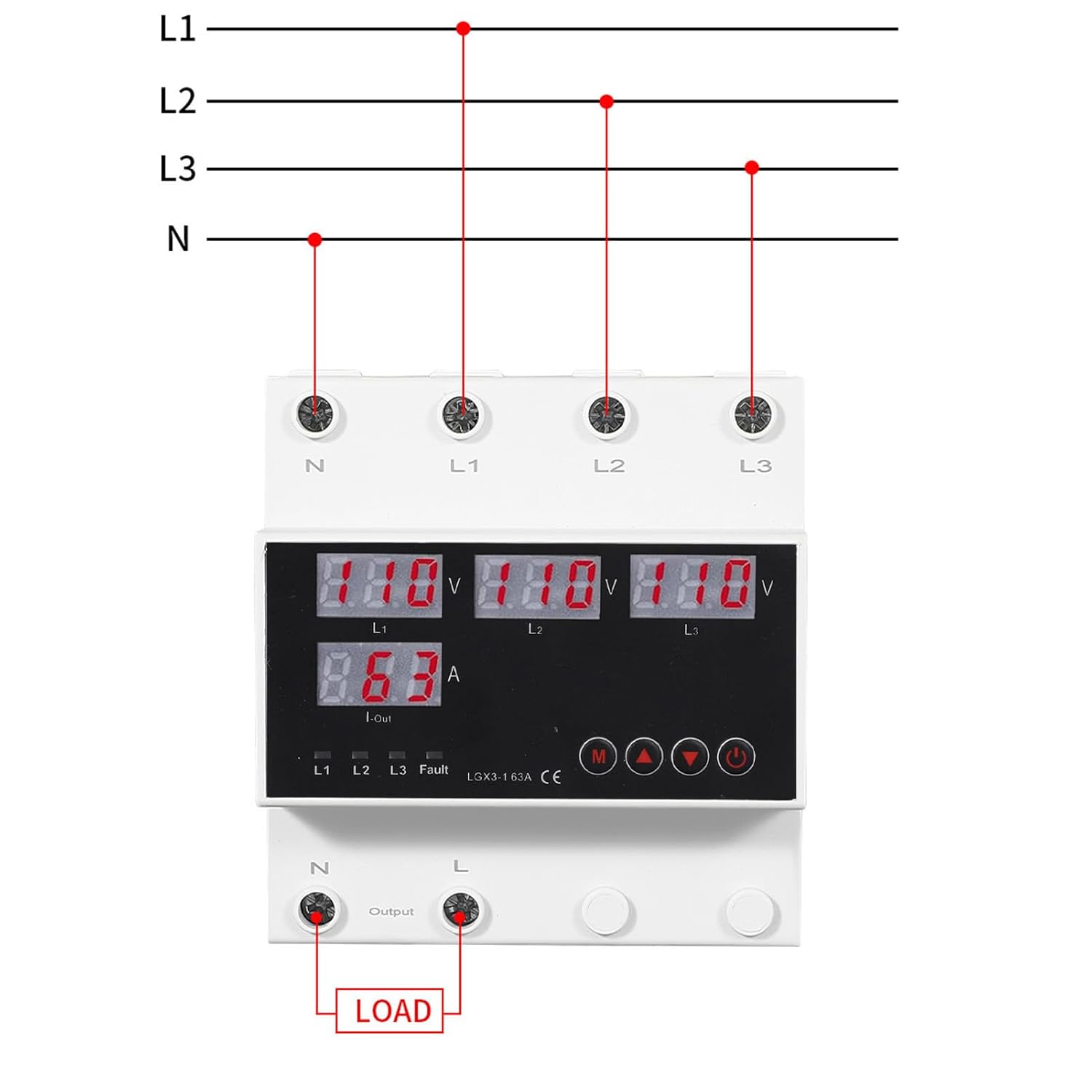
Figure 5.1: Wiring diagram for connecting the automatic transfer switch to power sources and load.
6. Operation
After successful installation and power-up, the ATS will display current voltage and current readings. The device operates automatically to manage power transfer.
6.1 Powering On/Off
- Once wired and power is supplied, the device will automatically power on and display readings.
- Use the power button (usually marked with a circle and vertical line) on the front panel to manually switch the device on or off if needed for maintenance or specific operational requirements.
6.2 Understanding the Display
The digital display shows real-time voltage (V) for L1, L2, L3, and current (A) for the output. Status indicators (L1, L2, L3, Fault) provide operational feedback.
6.3 Setting Parameters
The CHLT-GX2 allows customization of various parameters using the 'M' (Menu) button and arrow buttons (up/down).
- Accessing Menu: Press the 'M' button to enter the parameter setting mode.
- Navigating Parameters: Use the up/down arrow buttons to scroll through different settings such as Auto Reclosing Delay (Ton), Return Priority Stage Delay, Overvoltage Trip Delay, Undervoltage Trip Delay, etc.
- Adjusting Values: When a parameter is selected, press 'M' again to enter edit mode, then use the up/down arrows to change the value. Press 'M' to confirm and save the setting.
- Priority Setting: The device prioritizes power sources (L1>L2>L3) and allows for adjustable voltage thresholds to determine when switching occurs. Refer to the detailed parameter list in Section 4 for specific ranges.
7. Maintenance
Regular maintenance ensures the longevity and reliable operation of your ATS.
- Cleaning: Periodically clean the exterior of the device with a dry, soft cloth. Do not use abrasive cleaners or solvents. Ensure no dust accumulates in ventilation openings.
- Inspection: Annually inspect all wiring connections for tightness and signs of wear or corrosion. Check for any physical damage to the device casing or terminals.
- Environmental Conditions: Ensure the operating environment remains within the specified temperature and humidity ranges to prevent premature failure.
8. Troubleshooting
If you encounter issues with your Hilitand Automatic Transfer Switch, refer to the following common problems and solutions:
| Problem | Possible Cause | Solution |
|---|---|---|
| Device does not power on | No input power; Loose wiring; Internal fault | Check power supply; Verify all wiring connections; Contact support if power is present but device remains off. |
| ATS not switching power sources | Voltage outside set thresholds; Delay settings; Faulty power source | Check input voltages; Review and adjust delay and voltage threshold settings; Verify backup power source functionality. |
| "Fault" indicator illuminated | Overcurrent; Over/Undervoltage; Internal error | Check load current; Verify input voltages are within acceptable range; Disconnect power, wait, then reconnect. If fault persists, contact support. |
| Inaccurate voltage/current readings | Loose connections; Sensor issue | Check wiring connections; Contact support for calibration or repair. |
If the problem persists after attempting these solutions, please contact Hilitand customer support for further assistance.
9. Warranty and Support
Hilitand products are manufactured to high-quality standards. For warranty information, please refer to the documentation provided with your purchase or visit the official Hilitand website. For technical support, troubleshooting assistance, or spare parts, please contact Hilitand customer service through their official channels.
Hilitand Official Store: Visit Hilitand Store on Amazon


