
1. Introduction
The Sunshine DT-17N is a compact and versatile digital multimeter designed for accurate electrical measurements. This device is suitable for a wide range of applications, from basic household electrical checks to professional industrial testing. It features a clear LCD display and various measurement functions, including voltage, current, resistance, frequency, capacitance, and temperature. This manual provides essential information for the safe and effective operation and maintenance of your DT-17N multimeter.
2. Safety Information
Always observe safety precautions when using electrical testing equipment.
- Read and understand all instructions before use.
- Do not exceed the maximum input limits for any function.
- Ensure test leads are in good condition and properly connected.
- Never measure voltage on a circuit with the function selector set to current, resistance, or continuity.
- Exercise extreme caution when working with live circuits. High voltages can be dangerous.
- Replace batteries promptly when the low battery indicator appears to ensure accurate readings.
- Do not operate the multimeter if it appears damaged or is not functioning correctly.
3. Product Overview
Familiarize yourself with the components of your Sunshine DT-17N Digital Multimeter:
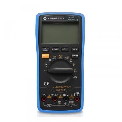
Image Description: A blue and black Sunshine DT-17N Digital Multimeter. The image highlights and labels various parts of the device. Key components include the large LCD display at the top, the central rotary function selector switch, and the input jacks at the bottom. Labels point to: LCD display, Manual range selection, Data retention key (HOLD), Function hold key (SELECT), Relative selection key (RELA), Switch key (Hz%), Measurement key (MAXMIN), Function selector switch, Current output (10A), 10A current output, mA current input, COM input, and Voltage/resistance/capacitance/frequency/temperature input port (VΩHz).
Key Components:
- LCD Display: Shows measurement readings, units, and various indicators.
- Function Selector Switch: Rotary switch to select the desired measurement function (e.g., Voltage, Current, Resistance, Capacitance, Frequency, Temperature, Diode, Continuity).
- HOLD Button: Freezes the current reading on the display.
- RANGE Button: Allows manual selection of measurement range instead of auto-ranging.
- RELA (Relative) Button: Measures the difference between a stored value and the current reading.
- Hz % Button: Toggles between frequency (Hz) and duty cycle (%) measurement in AC modes.
- MAXMIN Button: Records and displays the maximum and minimum values during a measurement session.
- SELECT Button: Toggles between different functions within a single rotary switch position (e.g., AC/DC voltage, Diode/Continuity).
- Input Jacks:
- COM (Common) Jack: For the black test lead (negative).
- VΩHz Jack: For the red test lead (positive) for voltage, resistance, frequency, capacitance, and temperature measurements.
- mA Jack: For the red test lead (positive) for milliampere current measurements.
- 10A Jack: For the red test lead (positive) for high current (up to 10A) measurements.
4. Setup
4.1. Battery Installation
- Ensure the multimeter is turned OFF.
- Locate the battery compartment cover on the back of the unit.
- Unscrew the retaining screw(s) and remove the cover.
- Insert the required batteries (typically 9V, refer to the battery compartment for specifics) observing correct polarity (+/-).
- Replace the battery cover and secure it with the screw(s).
4.2. Connecting Test Leads
- Always connect the black test lead to the COM input jack.
- Connect the red test lead to the appropriate input jack based on the desired measurement:
- For Voltage, Resistance, Capacitance, Frequency, or Temperature: Use the VΩHz jack.
- For milliampere current: Use the mA jack.
- For 10 Ampere current: Use the 10A jack.
5. Operating Instructions
5.1. Powering On/Off
Turn the function selector switch from the "OFF" position to any desired measurement function to power on the multimeter. To power off, turn the switch back to "OFF". The multimeter features an Auto Power Off (APO) function to conserve battery life.
5.2. Measuring DC Voltage (VDC)
- Connect the black test lead to COM and the red test lead to VΩHz.
- Turn the function selector switch to the V (DC Voltage) position. If there's a combined AC/DC voltage setting, press the SELECT button to choose DC.
- Connect the test probes across the component or circuit to be measured, observing polarity.
- Read the voltage value on the LCD display.
5.3. Measuring AC Voltage (VAC)
- Connect the black test lead to COM and the red test lead to VΩHz.
- Turn the function selector switch to the V~ (AC Voltage) position. If there's a combined AC/DC voltage setting, press the SELECT button to choose AC.
- Connect the test probes across the component or circuit to be measured.
- Read the voltage value on the LCD display.
5.4. Measuring DC Current (ADC)
Caution: Never connect the multimeter in parallel with a voltage source when measuring current. Always connect in series.
- Determine the expected current range. For currents up to 200mA, connect the red lead to mA. For currents up to 10A, connect the red lead to 10A. The black lead always connects to COM.
- Turn the function selector switch to the appropriate A (DC Current) position (e.g., mA or 10A).
- Open the circuit where current is to be measured and connect the multimeter in series.
- Read the current value on the LCD display.
5.5. Measuring Resistance (Ω)
Caution: Ensure the circuit or component is de-energized before measuring resistance.
- Connect the black test lead to COM and the red test lead to VΩHz.
- Turn the function selector switch to the Ω (Resistance) position.
- Connect the test probes across the component.
- Read the resistance value on the LCD display.
5.6. Continuity Test
- Connect the black test lead to COM and the red test lead to VΩHz.
- Turn the function selector switch to the Continuity (often shared with Diode or Resistance) position. Press SELECT if necessary.
- Connect the test probes across the circuit or component.
- A continuous beep indicates a low resistance path (continuity). The display will show the resistance value.
5.7. Diode Test
- Connect the black test lead to COM and the red test lead to VΩHz.
- Turn the function selector switch to the Diode (often shared with Continuity) position. Press SELECT if necessary.
- Connect the red probe to the anode and the black probe to the cathode of the diode.
- The display will show the forward voltage drop. Reverse the probes; an open circuit (OL) reading indicates a good diode.
5.8. Capacitance Measurement
Caution: Discharge capacitors before testing to avoid damage to the multimeter.
- Connect the black test lead to COM and the red test lead to VΩHz.
- Turn the function selector switch to the Capacitance (often denoted by a capacitor symbol) position.
- Connect the test probes across the capacitor.
- Read the capacitance value on the LCD display.
5.9. Frequency (Hz) and Duty Cycle (%) Measurement
- Connect the black test lead to COM and the red test lead to VΩHz.
- Turn the function selector switch to the Hz position (or a shared function like AC Voltage where Hz is an option).
- Press the Hz % button to toggle between frequency and duty cycle measurement.
- Connect the test probes across the signal source.
- Read the frequency or duty cycle value on the LCD display.
5.10. Temperature Measurement
If your multimeter includes a temperature probe (thermocouple), follow these steps:
- Ensure the multimeter is OFF.
- Connect the temperature probe to the COM and VΩHz jacks, observing polarity (usually indicated on the probe).
- Turn the function selector switch to the Temperature (often denoted by a thermometer symbol) position.
- Place the tip of the temperature probe on or near the object whose temperature is to be measured.
- Read the temperature value on the LCD display.
6. Maintenance
6.1. Cleaning
Wipe the case with a damp cloth and mild detergent. Do not use abrasives or solvents. Ensure the multimeter is completely dry before use.
6.2. Battery Replacement
When the low battery indicator appears on the display, replace the batteries as described in the "Battery Installation" section (4.1). Use only the specified battery type.
6.3. Fuse Replacement
If the current measurement function stops working, the fuse may be blown. Refer to the multimeter's internal diagram or contact support for fuse specifications and replacement instructions. Always replace with a fuse of the identical type and rating.
6.4. Storage
If the multimeter is not used for an extended period, remove the batteries to prevent leakage. Store the device in a cool, dry place, away from direct sunlight and extreme temperatures.
7. Troubleshooting
- No Display / Faint Display: Check battery charge. Replace batteries if low. Ensure batteries are installed with correct polarity.
- Incorrect Readings:
- Ensure the correct function is selected on the rotary switch.
- Verify test leads are connected to the correct input jacks.
- Check for damaged test leads.
- Ensure the circuit is de-energized for resistance/continuity measurements.
- "OL" (Overload) Display: The measured value exceeds the selected range or the maximum input limit. Select a higher range or a different measurement function.
- Current Measurement Not Working: Check the fuse. Replace if blown (refer to fuse replacement instructions).
8. Specifications
| Feature | Detail |
|---|---|
| Model | DT-17N |
| Display Counts | 2000 Counts |
| Measurement Type | Digital Multimeter |
| Power Source | Battery Powered |
| Color | Blue |
| Included Components | DIGITAL MULTIMETER (and typically test leads, battery, manual) |
| Country of Origin | India |
| Manufacturer | SPARKGLOBAL |
9. Warranty and Support
For warranty information and technical support, please refer to the documentation provided with your purchase or contact the retailer/manufacturer directly. Keep your purchase receipt as proof of purchase.
Manufacturer: SPARKGLOBAL
