
1. Introduction
The Espressif ESP32-P4-Function-EV-Board is a multimedia development board designed around the powerful ESP32-P4 chip. This board is engineered for developing low-cost, high-performance, and low-power network-connected audio and video products. It integrates a dual-core RISC-V processor, supports up to 32 MB PSRAM, and includes advanced peripherals such as USB 2.0, MIPI-CSI/DSI, and H.264 Encoder. The board also features a 2.4 GHz Wi-Fi 6 & Bluetooth 5 (LE) module (ESP32-C6-MINI-1) and a 7-inch capacitive touch screen with 1024x600 resolution.
This manual provides essential information for setting up, operating, and maintaining your ESP32-P4-Function-EV-Board.
2. Key Features
- Processor: Dual-core RISC-V processor (ESP32-P4).
- Wireless Connectivity: ESP32-C6-MINI-1 module providing Wi-Fi 6 and Bluetooth 5 (LE).
- Memory: Integrated 32 MB PSRAM and 16 MB Flash.
- Multimedia Support: High-definition camera processing (MIPI-CSI) and H.264 hardware encoding.
- Display Support: High-resolution display (MIPI-DSI) with graphics acceleration.
- Peripherals: USB 2.0, MicroSD Card Slot, 100 Mbps Ethernet, 55 Programmable GPIOs.
3. What's Included
The ESP32-P4-Function-EV-Board Kit typically includes the following components:
- ESP32-P4-Function-EV-Board Main Board (with ESP32-P4 chip and ESP32-C6 module).
- 7-inch LCD with 1024x600 resolution, Capacitive Touch Screen with MIPI-DSI.
- 2MP Camera with MIPI-CSI.
- LCD Adapter.
- Camera Adapter.
- Accessories bag (includes DuPont Wires, Flat Flex Cables, and Brass Standoffs).
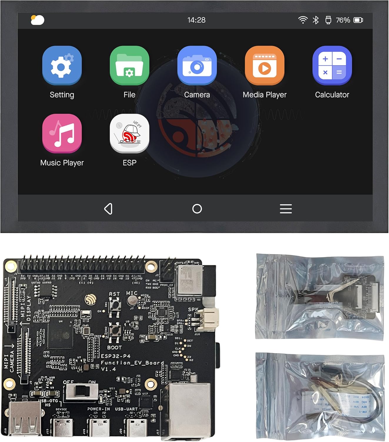
Image: Contents of the ESP32-P4-Function-EV-Board kit, including the main board, LCD, camera, and various cables.
4. Setup Guide
4.1 Board Overview
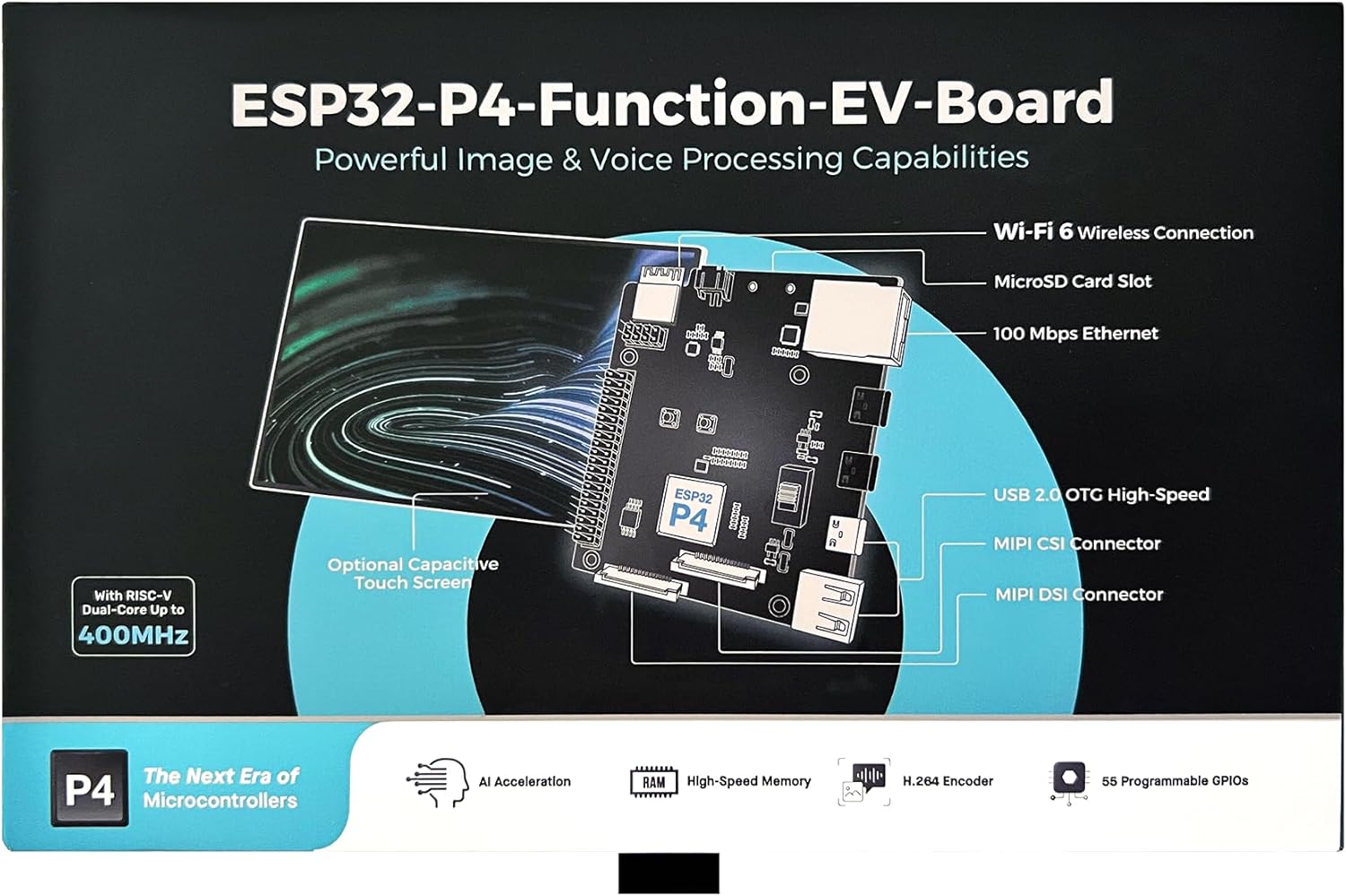
Image: ESP32-P4-Function-EV-Board diagram with labeled components.
Familiarize yourself with the board layout. Key interfaces include:
- MIPI CSI Connector: For connecting the camera module.
- MIPI DSI Connector: For connecting the LCD display.
- USB 2.0 OTG High-Speed: For data transfer and power.
- MicroSD Card Slot: For external storage.
- 100 Mbps Ethernet: For wired network connectivity.
- GPIO Pins: For various input/output operations.
4.2 Connecting the Display and Camera
- Connect the LCD: Use the provided Flat Flex Cable (FFC) and LCD Adapter to connect the 7-inch LCD to the MIPI DSI connector on the main board. Ensure the cable is inserted correctly and securely.
- Connect the Camera: Use the provided FFC and Camera Adapter to connect the 2MP Camera to the MIPI CSI connector on the main board. Verify proper orientation and secure connection.
4.3 Powering the Board
The board can be powered via the USB 2.0 OTG port. Connect a compatible USB power supply (e.g., 5V, 2A) to the USB port labeled "USB-UART" or "USB OTG".
Caution: Ensure the power supply voltage and current ratings are compatible with the board to prevent damage.
5. Operating Instructions
5.1 Initial Boot-up
- After connecting power, the board should begin its boot sequence.
- Observe the LCD screen for display output. The pre-installed firmware may show a graphical user interface (GUI).
- If the screen remains blank, check all cable connections and power supply.

Image: Example of the graphical user interface on the 7-inch touch screen.
5.2 Software Development
The ESP32-P4-Function-EV-Board supports various development environments. Refer to the official Espressif documentation and SDKs for detailed programming guides. Common operating systems supported include Linux.
- Espressif IDF: The Espressif IoT Development Framework is the official framework for ESP32 series chips.
- Toolchains: Ensure you have the correct RISC-V toolchain installed for compiling your applications.
- Flashing Firmware: Use Espressif's esptool.py or other compatible tools to flash custom firmware to the board via the USB-UART interface.
5.3 Network Connectivity
The ESP32-C6-MINI-1 module provides Wi-Fi 6 and Bluetooth 5 (LE) connectivity. The board also features a 100 Mbps Ethernet port.
- Wi-Fi: Configure Wi-Fi settings through your application or the board's operating system.
- Bluetooth: Utilize Bluetooth for short-range wireless communication with compatible devices.
- Ethernet: Connect an Ethernet cable to the RJ45 port for a stable wired network connection.
6. Target Applications
The ESP32-P4-Function-EV-Board is suitable for prototyping and developing a wide range of products, including:
- IP Cameras and Face Tracking Cameras
- Smart Locks and Video Doorbell Cameras
- Smart Home Control Panels, Appliance Control Screens, and Industrial Control Screens
- LED Advertising Screens, LCD Digital Price Tags, and Kiosks
- USB Hubs, Robotic Control, and Appliance Control Devices
- Two-wheel Vehicle Dashboards
7. Specifications
| Feature | Detail |
|---|---|
| Processor | ESP32-P4 (Dual-core RISC-V) |
| Wireless Module | ESP32-C6-MINI-1 (Wi-Fi 6, Bluetooth 5 LE) |
| RAM | 32 MB PSRAM |
| Flash Memory | 16 MB |
| Display | 7-inch Capacitive Touch Screen, 1024x600 resolution (MIPI-DSI) |
| Camera | 2MP (MIPI-CSI) |
| USB | USB 2.0 OTG High-Speed |
| Ethernet | 100 Mbps |
| Operating System | Linux (supported) |
| Dimensions | 8 x 5 x 2.7 inches |
| Item Weight | 1.1 pounds |
8. Maintenance
- Cleaning: Use a soft, dry cloth to clean the board and display. Avoid using liquids or abrasive cleaners.
- Storage: Store the board in a dry, anti-static environment when not in use.
- Firmware Updates: Regularly check the official Espressif website for firmware updates to ensure optimal performance and security.
- Handling: Handle the board by its edges to avoid touching sensitive components and static discharge.
9. Troubleshooting
9.1 Common Issues and Solutions
- Board not powering on:
- Verify the USB power cable is securely connected.
- Ensure the power supply provides adequate voltage (5V) and current.
- Check for any visible damage to the board or power port.
- Display not showing output:
- Confirm the MIPI DSI FFC cable is correctly and firmly seated at both the LCD and board ends.
- Ensure the LCD Adapter is properly connected.
- Check if the board is receiving power and booting correctly (e.g., by observing status LEDs if available).
- Camera not detected:
- Verify the MIPI CSI FFC cable and Camera Adapter are correctly connected.
- Ensure the software application or operating system is configured to recognize and initialize the camera.
- Wi-Fi/Bluetooth connectivity issues:
- Check antenna connections if external antennas are used.
- Verify network configuration in your software.
- Ensure the Wi-Fi access point or Bluetooth device is within range and functioning correctly.
9.2 Further Assistance
For more complex issues or detailed technical support, please refer to the official Espressif documentation, community forums, or contact Espressif support directly.
10. Warranty and Support
Espressif products typically come with a standard manufacturer's warranty covering defects in materials and workmanship. For specific warranty terms and conditions, please refer to the documentation provided with your purchase or visit the official Espressif website.
For technical support, resources, and community forums, please visit the Espressif Systems website.


