1. Introduction
This manual provides detailed instructions for the assembly, operation, and maintenance of the Irfora MAX038 Signal Generator DIY Kit. The MAX038 is a high-speed op-amp based function generator capable of producing sine, triangle, rectangular, and sawtooth waveforms with a frequency range of 1Hz to 20MHz. This kit is designed for enthusiasts and professionals to build their own signal generator for various electronic testing and development applications.
2. Safety Information
- Always ensure the power supply is disconnected before assembling or disassembling components.
- Use appropriate soldering equipment and ensure proper ventilation when soldering.
- Avoid touching live circuits when the device is powered on.
- Do not exceed the recommended operating voltage of 9-15V.
- Keep the kit away from moisture and extreme temperatures.
- This product contains small parts and is not suitable for children without adult supervision.
3. Package Contents
The Irfora MAX038 Signal Generator DIY Kit includes all necessary components for assembly. Please verify that all parts listed below are present before beginning assembly.
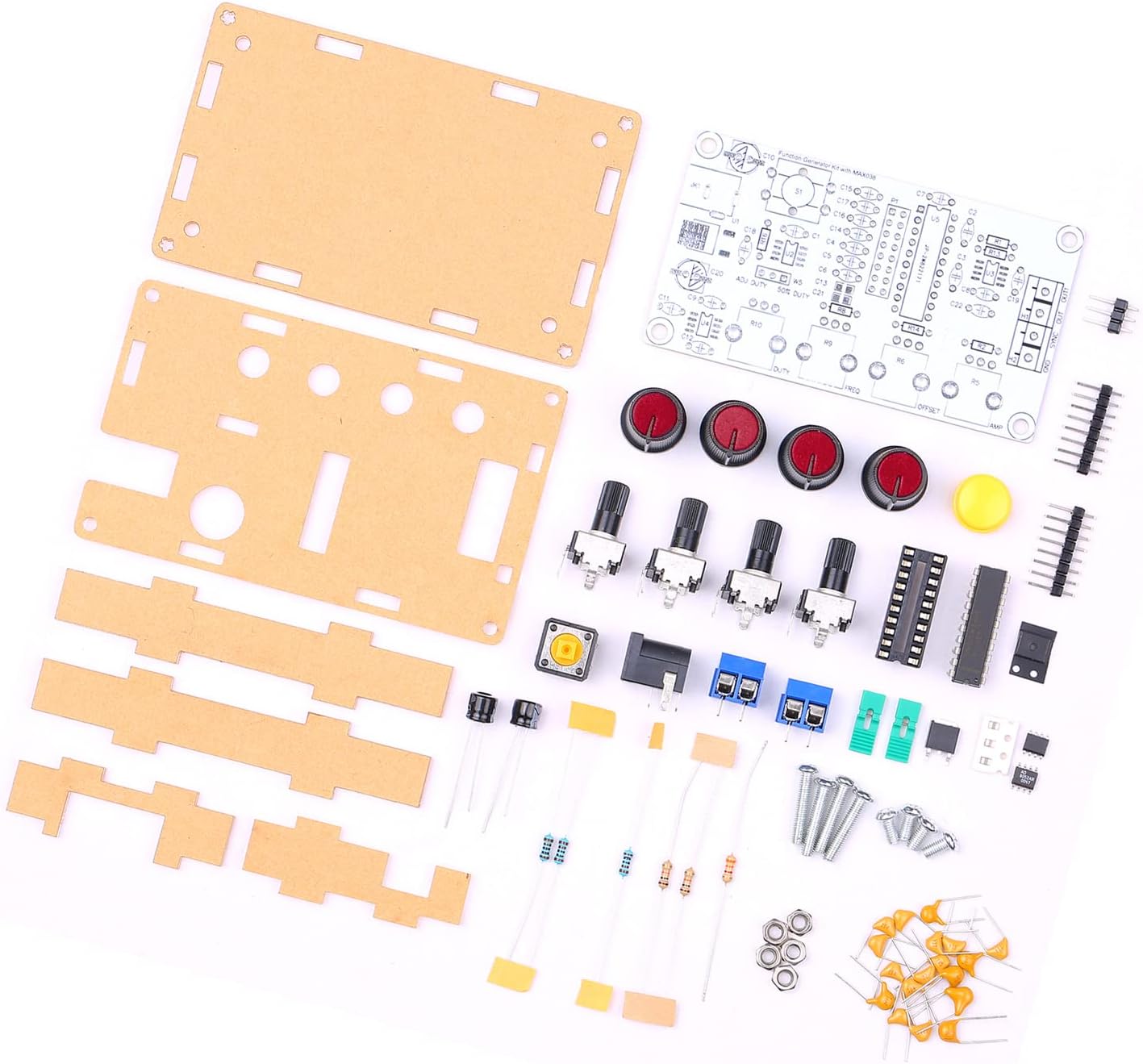
Image: All components of the Irfora MAX038 Signal Generator DIY Kit, including the PCB, acrylic casing parts, potentiometers, switches, ICs, resistors, capacitors, and fasteners.
- MAX038 PCB (Printed Circuit Board)
- Acrylic casing parts
- Potentiometers (for frequency, duty cycle, offset, and amplitude adjustment)
- Toggle switches (for waveform selection)
- Integrated Circuits (ICs)
- Resistors, Capacitors, Diodes
- Terminal blocks and connectors
- Power jack
- Fasteners (screws, nuts)
4. Setup and Assembly
Assembly of the MAX038 Signal Generator DIY Kit requires basic soldering skills and tools. Follow these steps carefully:
- Component Identification: Before starting, identify all components using the provided circuit diagram (if included) and the component list.
- Solder Smallest Components First: Begin by soldering the smallest components to the PCB, such as resistors and diodes, followed by capacitors. Pay attention to polarity for electrolytic capacitors and diodes.
- Install IC Sockets: Solder the IC sockets to the PCB. Ensure correct orientation. Insert the MAX038 IC and other ICs into their respective sockets after all soldering is complete to prevent heat damage.
- Solder Larger Components: Proceed with soldering the potentiometers, switches, terminal blocks, and power jack. Ensure they are flush with the PCB and correctly oriented.
- Inspect Solder Joints: After soldering all components, carefully inspect all solder joints for bridges, cold joints, or poor connections.
- Assemble Acrylic Casing: Once the PCB assembly is complete and verified, mount the PCB into the acrylic casing using the provided screws and standoffs. Ensure all potentiometers and switches align with the holes in the top panel.

Image: The fully assembled Irfora MAX038 Signal Generator, showcasing the clear acrylic casing and control knobs.
Power Supply Connection
Connect a DC power supply (9V to 15V) to the power jack or the designated power input terminals. The circuit operates on a single power supply, with an internal power management IC providing dual power for the op-amp, ensuring signal integrity.
5. Operating Instructions
The MAX038 Signal Generator allows for the creation and adjustment of various waveforms. Familiarize yourself with the controls:

Image: Top view of the assembled MAX038, highlighting the four main control knobs for frequency, duty cycle, offset, and amplitude, along with waveform selection switches.
- Frequency Adjustment: Use the 'FREQ' potentiometer to adjust the output frequency from 1Hz to 20MHz.
- Waveform Selection: Use the toggle switches to select between sine, triangle, rectangular, and sawtooth waveforms. The kit supports both forward and reverse sawtooth outputs.
- Duty Cycle Adjustment: The 'DUTY' potentiometer allows adjustment of the duty cycle from 15% to 85% for rectangular and sawtooth waveforms.
- DC Offset Adjustment: The 'OFFSET' potentiometer controls the DC offset of the output signal, adjustable from -5V to +5V.
- Amplitude Adjustment: The 'AMP' potentiometer adjusts the peak-to-peak amplitude of the output signal from 0.1V to 9.5V (with a 9V operating voltage).
- SYNC Output: The device provides a SYNC output signal, which can be used for synchronization with other equipment.
6. Maintenance
To ensure the longevity and optimal performance of your MAX038 Signal Generator, follow these maintenance guidelines:
- Cleaning: Use a soft, dry cloth to clean the exterior of the device. Avoid using liquid cleaners or solvents, as they may damage the acrylic casing or electronic components.
- Storage: Store the device in a cool, dry place away from direct sunlight and excessive dust.
- Inspection: Periodically inspect the power cable and connections for any signs of wear or damage.
- Component Replacement: If any component fails, replace it with an equivalent part. Consult the circuit diagram for specifications.
7. Troubleshooting
If you encounter issues with your MAX038 Signal Generator, refer to the following troubleshooting steps:
- No Output Signal:
- Check power supply connection and ensure it is within the 9-15V range.
- Verify all solder joints, especially for the MAX038 IC and output stage.
- Ensure waveform selection switches are correctly set.
- Incorrect Frequency/Amplitude:
- Ensure potentiometers are functioning correctly and not at their limits.
- Check for any short circuits or open circuits on the PCB.
- Distorted Waveform:
- Verify the power supply is stable and free from ripple.
- Check for any faulty capacitors or resistors.
- Ensure the op-amp is correctly seated in its socket and not damaged.
8. Specifications
The following are the technical specifications for the Irfora MAX038 Signal Generator DIY Kit:

Image: Detailed product parameters for the MAX038 signal generator, including frequency range, duty cycle, and output linearity.
| Feature | Specification |
|---|---|
| Product Name | MAX038 Signal Generator |
| Material | PCB + Acrylic |
| Frequency Adjustment Range | 1Hz ~ 20MHz |
| Duty Cycle Adjustment Range | 15% ~ 85% |
| Low Loss True Sine Wave | 0.75% |
| Triangle Wave Output Linearity | 0.1% |
| Low Impedance Output Buffer | 0.1Ω |
| DC Offset Adjustable | -5V ~ +5V |
| Adjustable Output Amplitude | 0.1V ~ 9.5VPP (operating voltage 9V) |
| Single Power Supply Operation | 9V ~ 15V |
| Temperature Drift | 200ppm/°C |
| Output Waveforms | Sine, Triangle, Rectangular, Forward/Reverse Sawtooth |
| SYNC Output | Yes |
| Product Dimensions | 99 * 59 * 32mm / 3.90 * 2.32 * 1.26in |
| Item Weight | 82g / 2.90oz |

Image: Physical dimensions of the assembled MAX038 signal generator, showing length, width, and height measurements.
9. Warranty and Support
This Irfora MAX038 Signal Generator DIY Kit is provided as a component kit. For any questions regarding assembly, operation, or technical support, please contact the manufacturer or your point of purchase. Please retain your proof of purchase for any warranty claims, if applicable.

