
1. Introduction
This manual provides detailed instructions for the installation, operation, and maintenance of the Aoleaby HY-502 LCD 3 Phase Multimeter. This digital display panel meter is designed for accurate measurement and monitoring of electrical parameters in three-phase systems, utilizing a current transformer for precise readings.
The HY-502 is a robust and reliable device, suitable for various industrial and commercial applications requiring precise electrical monitoring.

Image 1.1: The Aoleaby HY-502 LCD 3 Phase Multimeter shown with its accompanying current transformers. The meter features an LCD display and control buttons.
2. Product Features
- Digital Display: Clear LCD for easy reading of multiple parameters.
- Three-Phase Measurement: Designed for comprehensive monitoring of three-phase electrical systems.
- Current Transformer Integration: Built-in input coil for small, light, and easy installation of current transformers.
- Robust Construction: Fully enclosed design ensures good mechanical properties and environmental resistance.
- High Voltage Isolation: Strong voltage isolation capability for enhanced safety and reliability.
- Accurate Measurement: Provides highly accurate current measurement across various ranges and conditions.
- Safety Features: Monitors and protects against equipment overloads, short circuits, and other current anomalies.
- Reliable Performance: Stable performance and long-term reliability for demanding industrial environments.

Image 2.1: Overview of different Aoleaby multimeter models, highlighting features such as solid shell, flame retardant properties, intelligence, Class 0.5 accuracy, and multifunctionality. Icons represent frequency, RS485 communication, active/reactive functions, current/voltage, and power factor.
3. Specifications
| Parameter | Value |
|---|---|
| Model Number | HY-500 (Base Model, HY-502 is a specific configuration) |
| Display Type | Digital Only (LCD) |
| Phase | Three Phase |
| Measuring Energy Range | AC85V~265V / DC100V-300V / AC220V |
| Accuracy Class | 0.5, 1.0, 2.0 (depending on specific measurement) |
| Operating Temperature | -20°C to 55°C |
| Dimensions | 96mm x 96mm |
| Wiring Mode | 3 Phase 4 Wires / 3 Phase 3 Wires |
| Related Voltage | AC57.7V, AC100V, AC220V, AC380V |
| Frequency | 45-65Hz |
| Storage Temperature | -25°C to 70°C |
| Item Weight | Approximately 5.51 pounds (2.5 kg) |
| Package Dimensions | 1.18 x 0.79 x 0.39 inches (30 x 20 x 10 mm) |

Image 3.1: A selection of current transformers (CTs) of different sizes, designed for use with the Aoleaby HY-502 multimeter. These CTs are essential for measuring high currents safely.
4. Setup and Installation
Safety Precautions: Before installation, ensure that the power supply is disconnected. Installation should only be performed by qualified personnel. Always follow local electrical codes and regulations.
- Mounting the Meter: The HY-502 is a panel-mount meter with dimensions of 96x96mm. Ensure the panel cutout matches the meter's dimensions for a secure fit.
- Wiring the Current Transformers (CTs): Connect the primary side of the CTs to the main current path of the circuit to be measured. Connect the secondary side of the CTs to the current input terminals (Ia, Ib, Ic) on the multimeter. Ensure correct polarity.
- Wiring the Voltage Inputs: Connect the voltage input terminals (Ua, Ub, Uc, Un) to the respective phases and neutral of the three-phase system. Refer to the terminal layout diagram for specific connections.
- Auxiliary Power Supply: Connect the auxiliary power supply (AC85V~265V or DC100V-300V) to the designated power terminals (L, N).
- Communication (Optional): If using RS485 communication, connect the A and B terminals to the RS485 network.
- Switching Inputs/Outputs (Optional): Connect external devices to the switching input/output terminals as required for control or monitoring functions.
4.1 Terminal Layout and Model Meaning
Refer to the diagram below for detailed terminal connections and understanding the model coding system.
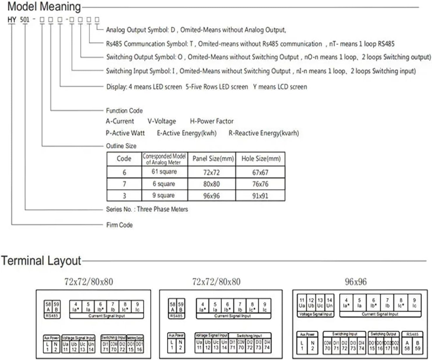
Image 4.1: This diagram illustrates the model coding system for the HY-501 series (applicable to HY-502) and provides detailed terminal layouts for different meter sizes (72x72, 80x80, 96x96). It shows connections for auxiliary power, voltage input, current signal input, switching input/output, and RS485 communication.
Model Meaning Breakdown:
- Analog Output Symbol (D): Indicates analog output. Omitted means no analog output.
- RS485 Communication Symbol (T): Indicates RS485 communication. Omitted means no RS485 communication. nT means 1 loop RS485.
- Switching Output Symbol (O): Indicates switching output. Omitted means no switching output. nO means n loops switching output.
- Switching Input Symbol (I): Indicates switching input. Omitted means no switching input. nI means n loops switching input.
- Display: 4 means LED screen, 5 means Five Rows LED screen, Y means LCD screen.
Function Codes:
- A: Current
- V: Voltage
- H: Power Factor
- P: Active Watt
- E: Active Energy (kWh)
- R: Reactive Energy (kvarh)
5. Operating Instructions
Once the meter is correctly installed and powered on, it will display various electrical parameters on its LCD screen.
5.1 Navigating the Display
The meter typically features navigation buttons (e.g., "SET", "<", ">", "Enter" or arrow keys) to cycle through different measurement screens and access settings.
- Default Display: Upon power-up, the meter usually displays primary parameters like voltage (V), current (A), and frequency (Hz).
- Scrolling Parameters: Use the "<" and ">" buttons to scroll through different measurement pages, which may include:
- Line-to-line and line-to-neutral voltages (Uab, Ubc, Uca, Ua, Ub, Uc)
- Phase currents (Ia, Ib, Ic)
- Active power (P), Reactive power (Q), Apparent power (S)
- Power factor (PF)
- Frequency (Hz)
- Active energy (kWh), Reactive energy (kvarh)
- Harmonic distortion (THD)
- Accessing Settings: Press the "SET" button (or similar) to enter the configuration menu. You may need to hold it for a few seconds.
5.2 Configuration Settings (Example)
Within the settings menu, you can typically configure parameters such as:
- CT Ratio: Set the primary and secondary current transformer ratios to ensure accurate current readings.
- PT Ratio: If potential transformers (PTs) are used, configure their ratios.
- Wiring Mode: Select between 3-phase 3-wire or 3-phase 4-wire configurations.
- Communication Settings: Configure RS485 parameters like baud rate, parity, and address.
- Alarm Thresholds: Set limits for various parameters to trigger alarms or switching outputs.
Always refer to the specific on-screen menu structure and the detailed wiring diagram (Image 4.1) for precise configuration steps.
6. Maintenance
The Aoleaby HY-502 multimeter is designed for minimal maintenance. However, regular checks can ensure its longevity and accurate operation.
- Cleaning: Keep the display and casing clean using a soft, dry cloth. Do not use abrasive cleaners or solvents.
- Connections: Periodically check all wiring connections for tightness and signs of corrosion. Loose connections can lead to inaccurate readings or operational issues.
- Environmental Conditions: Ensure the operating environment remains within the specified temperature and humidity ranges (-20°C to 55°C). Avoid exposure to excessive dust, moisture, or corrosive gases.
- Calibration: While the meter is factory calibrated, if accuracy concerns arise after prolonged use, professional calibration may be required.
7. Troubleshooting
| Problem | Possible Cause | Solution |
|---|---|---|
| Meter does not power on | No auxiliary power supply; Incorrect wiring; Blown fuse (external) | Check power connections; Verify wiring against diagram; Check external fuse. |
| Inaccurate current readings | Incorrect CT ratio setting; Incorrect CT wiring polarity; Faulty CT | Verify CT ratio in settings; Check CT wiring polarity; Test or replace CT. |
| Inaccurate voltage readings | Incorrect PT ratio setting (if applicable); Loose voltage connections | Verify PT ratio in settings; Tighten voltage connections. |
| Display shows "Err" or similar error code | Measurement range exceeded; Internal fault | Check input values against specifications; Contact technical support if persistent. |
| No communication via RS485 | Incorrect communication settings (baud rate, address); Wiring issue; Device not enabled | Verify RS485 settings; Check A/B wiring; Ensure RS485 function is enabled. |
8. Warranty and Support
For warranty information and technical support, please refer to the documentation provided with your purchase or contact Aoleaby customer service directly. Keep your purchase receipt as proof of purchase.
Manufacturer: Aoleaby
Model Number: HY-502
ASIN: B0D7CN8VX2