1. Introduction
This manual provides detailed instructions for the safe and effective use of your BSIDE 3-in-1 Handheld Oscilloscope Multimeter. This versatile device integrates the functions of a dual-channel oscilloscope, a true RMS multimeter, and a DDS signal generator, making it an essential tool for various electrical testing and measurement applications.

Figure 1: Overview of 3-in-1 functionality (Multimeter, DDS Generator, Oscilloscope).
2. Setup
2.1 Package Contents
Verify that all items listed below are present in your package:
- 1 x Handheld Oscilloscope Multimeter
- 1 x Oscilloscope Probe
- 1 x BNC to Double-Headed Alligator Clip Test Leads
- 1 x Test Leads
- 1 x Thermocouple
- 1 x Carrying Case
- 1 x Charging Cable
- 8 x Marker Rings
- 1 x Adjustment Tool
- 2 x IC Test Protection Caps
- 1 x User Manual
Note: The flexible AC current clamp is not included in the package and must be purchased separately if required.

Figure 2: The BSIDE Handheld Oscilloscope Multimeter and its complete set of accessories.
2.2 Device Overview
Familiarize yourself with the physical components of the device:
- Display: Features a 3.98-inch TFT LCD with a 178° full-viewing angle for clear readings.
- Input Ports: Dual channels for oscilloscope measurements and a dedicated DDS output port.
- Controls: Intuitive button layout for mode selection, adjustments, and data saving.
- Protection: Encased in a full-body soft silicone case for enhanced durability.
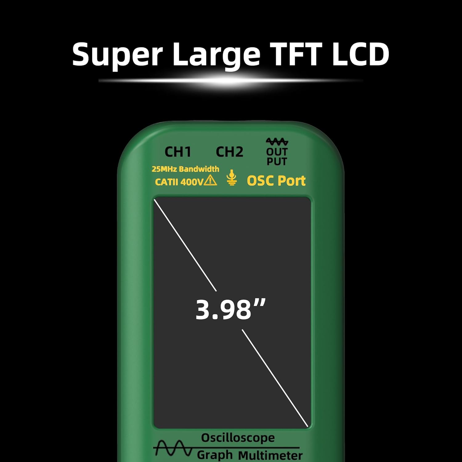
Figure 3: The device features a large 3.98-inch TFT LCD for optimal readability.

Figure 4: The top panel includes input ports for CH1, CH2, and DDS signal output.

Figure 5: The device is protected by a durable full-body soft silicone case.
3. Operating Instructions
3.1 Power On/Off
To power on the device, press and hold the power button (usually marked with a circle and a vertical line) until the screen illuminates. To power off, press and hold the same button until the device shuts down.
3.2 Mode Selection
The device offers three primary modes: Oscilloscope, Multimeter, and DDS Generator. Use the dedicated MODE button to cycle through these functions. The current mode will be displayed on the screen.
3.3 Oscilloscope Function
In Oscilloscope mode, the device displays waveforms for electrical signals. It features dual channels with a 25MHz bandwidth and a 208MSa/s real-time sample rate.
- Connecting Probes: Connect the oscilloscope probe to the appropriate channel input (CH1 or CH2) on the top of the device. Ensure a secure connection.
- Adjusting Settings: Use the navigation buttons to adjust vertical sensitivity (V/div), time base (s/div), and trigger settings. The AUTO button can be used for automatic waveform adjustment and display.
- Measurements: The screen will display various waveform parameters such as Vpp (peak-to-peak voltage), Vmax, Vmin, Vavg, Vrms, frequency, and duty cycle.
3.4 Multimeter Function
In Multimeter mode, the device performs various electrical measurements with 6000 counts display and True RMS capability.
- Connecting Test Leads: Connect the red and black test leads to the appropriate input jacks (e.g., VΩmA for voltage/resistance/current, COM for common ground).
- Measurement Types: The multimeter can measure:
- DC Voltage: Up to 1000V
- AC Voltage: Up to 750V
- DC Current: Up to 600mA
- AC Current: Up to 600mA (or up to 6000A with optional flexible AC current clamp)
- Resistance: Up to 60MΩ
- Capacitance: Up to 99.99mF
- Temperature: -20℃ to 1000℃ / -4℉ to 1832℉ (using thermocouple)
- Diode Test
- Continuity Test
- Range Selection: The device typically operates in auto-ranging mode, but manual range selection may be available via the controls.
3.5 DDS Generator Function
The DDS (Direct Digital Synthesis) Generator function allows you to output various waveforms for testing circuits.
- Connecting Output: Connect the DDS output port to your circuit using appropriate cables.
- Waveform Types: Select from sine wave, square wave, triangle wave, full wave, half wave, and sawtooth wave.
- Adjusting Parameters: Adjust the frequency (0-2MHz) and output amplitude (0.1-3V) using the device controls. For square waves, the duty cycle (1%-99%) can also be adjusted.
4. Maintenance
4.1 Battery Charging
The device is equipped with a 5000mAh rechargeable Li-ion battery. Use the provided charging cable to connect the device to a suitable USB power source. The battery indicator on the screen will show the charging status.

Figure 6: The device features a high-capacity 5000mAh rechargeable battery.
4.2 Cleaning and Storage
To clean the device, use a soft, dry cloth. Do not use abrasive cleaners or solvents. Store the device in its carrying case in a cool, dry place away from direct sunlight and extreme temperatures when not in use.
5. Troubleshooting
If you encounter issues with your device, please refer to the following common troubleshooting steps:
- Device not powering on: Ensure the battery is charged. Connect the device to a charger and attempt to power on again.
- Incorrect readings: Check that probes and test leads are correctly connected and not damaged. Verify that the correct measurement mode and range are selected.
- No waveform display: In oscilloscope mode, ensure the input signal is within the device's measurement range and that the trigger settings are appropriate. Use the AUTO button to attempt automatic adjustment.
For further assistance, please contact BSIDE customer support.
6. Specifications
| Feature | Specification |
|---|---|
| MAX Display | 6000 counts |
| Bandwidth | 25MHz |
| Channels | 2 |
| Real-time Sample Rate | 208MSa/s |
| Input Impedance | 1MΩ, @16pf |
| Maximum Input Voltage | 300V (DC+AC peak) |
| Horizontal SEC Range | 100ns/div - 20s/div |
| Vertical Sensitivity | 20mV/div - 100V/div |
| DC Voltage | 60mV (0.01mV ±(1%+5)); 600mV/6V/60V (0.1mV/0.001V/0.01V ±(0.8%+3)); 600V/1000V (0.1V ±(1%+5)) |
| AC Voltage | 60mV (0.01mV ±(1.2%+5)); 600mV/6V/60V (0.1mV/0.001V/0.01V ±(1%+3)); 600V/750V (0.1V/1V ±(1.2%+5)) |
| DC Current | 60mA/600mA (0.01mA/0.1mA ±(1%+3)) |
| AC Current | 60mA/600mA (0.01mA/0.1mA ±(1.2%+5)) |
| Flexible AC Current | 600A/6000A (0.1A/1A ±(1.0%+5)) |
| Resistance | 600Ω (0.1Ω ±(1.2%+5)); 6kΩ/60KΩ/600KΩ (0.001KΩ/0.01KΩ/0.1KΩ ±(1.0%+3)); 6MΩ (0.001MΩ ±(1.2%+5)); 60MΩ (0.01MΩ ±(1.5%+5)) |
| Capacitance | 999.9nF (0.1nF ±(5%+20)); 9.999µF/999.9µF (0.001µF/0.1µF ±(4.5%+5)); 99.99mF (0.01mF ±(5.0%+10)) |
| Temperature | -20℃~1000℃ / -4℉-1832℉ (1℃/1℉ ±(2.5%+5)) |
| Diode | Yes |
| Continuity | Yes |
| Output Waveforms | Sine wave, square wave, triangle wave, full wave, half wave, sawtooth wave, DC wave |
| Frequency Range (DDS) | 0-2MHz |
| Output Amplitude (DDS) | 0.1-3V |
| Square Wave Duty Cycle (DDS) | 1%-99% |
| Power | 2* Rechargeable Li-ion battery (5000mAh) |
| Size | 216.6 x 84.5 x 36 mm |
| Weight | 384g |
| Item Model Number | Dual Channel Oscilloscope Multimeter |
| Date First Available | June 18 2024 |
7. Warranty and Support
For warranty information, technical support, or service inquiries, please refer to the official BSIDE website or contact their customer service department directly. Keep your purchase receipt as proof of purchase for warranty claims.


