
Introduction
This manual provides comprehensive instructions for the safe installation, operation, and maintenance of your Connecticut Electric EGSPI50 50A Rainproof Generator Power Inlet Box. Please read this manual thoroughly before installation and use to ensure proper function and safety.
The EGSPI50 is designed to provide a safe and convenient connection point for a portable generator to supply power to your home's electrical system during outages, typically in conjunction with a transfer switch (sold separately).
Important Safety Information
WARNING: Risk of Electric Shock or Fire. Installation must be performed by a qualified electrician in accordance with all national and local electrical codes.
- Always disconnect power at the main service panel before installing or servicing this unit.
- Ensure the generator is properly grounded.
- Never backfeed power into the utility grid. This unit must be used with a properly installed transfer switch or interlock kit to prevent dangerous backfeeding.
- Do not operate the generator indoors or in enclosed spaces. Generator exhaust contains carbon monoxide, a colorless, odorless, and deadly gas.
- This product is for power inlet only. It is NOT for use as an outlet.
- Verify all connections are secure and properly insulated.
- Wear appropriate personal protective equipment (PPE) during installation.

Figure 1: Front view of the EGSPI50 Power Inlet Box with the cover open, displaying the 50A CS6375 receptacle and internal wiring. A warning label "DANGER - HIGH VOLTAGE - KEEP OUT" is visible on the top inside flap, and a notice "NOTICE FOR POWER INLET ONLY. NOT FOR USE AS AN OUTLET!" is on the bottom flap.
Product Overview and Components
The Connecticut Electric EGSPI50 is a robust, rainproof power inlet box designed for outdoor use. Key components include:
- NEMA Type 3R Enclosure: Provides protection against rain, sleet, and external ice formation.
- CS6375 Receptacle (SS2-50P Compatible): A 50-Amp, 120/240 VAC generator power inlet.
- Pre-wired Pigtail Connections: 6-inch pigtails for easy wiring to your transfer switch or main panel.
- Spring-loaded Door: Ensures weather protection when the cable is removed.
- Knockouts: 1/2-inch and 3/4-inch knockouts on multiple sides for flexible conduit entry.
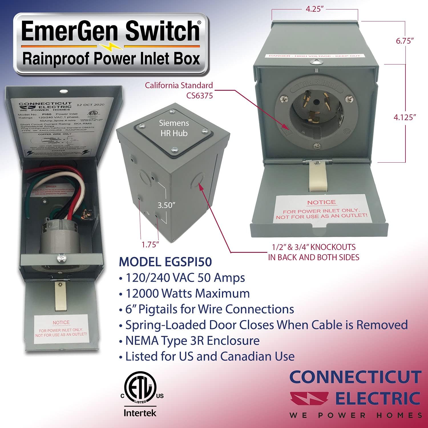
Figure 2: Detailed diagram of the EGSPI50, illustrating its dimensions (4.25"D x 6.75"W x 4.13"H), key features like the 120/240 VAC 50 Amps rating, 12000 Watts Maximum capacity, 6" Pigtails for Wire Connections, NEMA Type 3R Enclosure, and ETL Listing. It also shows the location of 1/2" & 3/4" knockouts.
Specifications
| Feature | Specification |
|---|---|
| Model Number | EGSPI50 |
| Amperage | 50 Amps |
| Voltage | 120/240 VAC |
| Maximum Capacity | 12,000 Watts |
| Receptacle Type | CS6375 (SS2-50P Compatible) |
| Enclosure Type | NEMA Type 3R Rainproof |
| Material | Alloy Steel |
| Color | Gray |
| Product Dimensions (DxWxH) | 4.25"D x 6.75"W x 4.13"H |
| Item Weight | 3.08 pounds |
| Installation Type | Screw-In |
| Certifications | UL Listed (Specification Met: Ul) |
Setup and Installation
Proper installation is critical for safety and performance. Consult a qualified electrician if you are not familiar with electrical wiring and local codes.
Tools and Materials Required (Not Included):
- Screwdriver set
- Wire strippers
- Conduit and fittings (appropriate size for knockouts)
- Electrical tape
- Mounting hardware (screws, anchors suitable for mounting surface)
- Personal Protective Equipment (PPE): Safety glasses, insulated gloves.
- Appropriate gauge wire (e.g., #6 AWG for 50A, if not using pre-wired pigtails or extending them)
- Transfer switch or interlock kit (required for safe operation)
Installation Steps:
- Select Location: Choose an outdoor location near your main electrical panel or transfer switch, ensuring it is easily accessible for generator connection and away from windows, doors, or vents to prevent exhaust fumes from entering the building. The NEMA Type 3R enclosure is rainproof, but avoid areas prone to standing water.
- Disconnect Power: CRITICAL STEP: Turn off the main breaker at your electrical service panel to completely de-energize the system before beginning any work. Verify power is off using a voltage tester.
- Mount the Inlet Box:
- Open the front cover of the inlet box.
- Position the box on the desired mounting surface.
- Mark the mounting hole locations.
- Drill pilot holes if necessary.
- Securely fasten the inlet box to the surface using appropriate mounting hardware.

Figure 3: Internal view of the EGSPI50, showing the pre-wired 6-inch pigtails (black, red, white, green) connected to the 50A receptacle. This image highlights the internal space available for wiring connections.
- Conduit and Wiring:
- Punch out the appropriate knockout(s) for your conduit entry.
- Install conduit and fittings to connect the inlet box to your transfer switch or main panel. Ensure all connections are watertight for outdoor use.
- Route the necessary electrical wires (typically 4-conductor, 6 AWG for 50A) through the conduit.
- Connect the wires from the conduit to the pre-wired pigtails inside the inlet box using appropriate wire connectors (e.g., wire nuts). Match colors: Black to Black, Red to Red, White to White (Neutral), Green to Green (Ground). Ensure connections are tight and secure.
- If extending the pigtails or connecting directly to the receptacle terminals (if applicable), ensure proper wire gauge and secure connections.

Figure 4: Side view of the EGSPI50 with the front cover open, providing a clearer view of the internal wiring and the conduit knockouts on the side of the enclosure.
- Connect to Transfer Switch/Panel: Complete the wiring connections at your transfer switch or main panel according to the manufacturer's instructions and local electrical codes.
- Final Inspection: Double-check all wiring connections for tightness and correct polarity. Ensure no bare wires are exposed. Close and secure the cover of the inlet box.
- Restore Power: Once all connections are verified and covers are secured, restore power at the main service panel.
Operating Instructions
This section outlines the general procedure for using your generator with the EGSPI50 Power Inlet Box. Always refer to your generator and transfer switch manuals for specific operating procedures.
- Prepare Generator: Ensure your portable generator is placed outdoors in a well-ventilated area, away from windows and doors, and on a level surface. Fill the fuel tank and check oil levels as per your generator's manual.
- Connect Generator Cable: Connect the appropriate generator power cord (e.g., 50A CS6364 or SS2-50P plug) to the receptacle on the EGSPI50 Power Inlet Box. Ensure the connection is secure and fully seated.
- Connect to Generator: Connect the other end of the generator power cord to your portable generator's 50A outlet.
- Start Generator: Start your generator according to its manufacturer's instructions. Allow it to warm up for a few minutes.
- Engage Transfer Switch: Operate your transfer switch or interlock kit to safely transfer power from the utility to the generator. Follow the specific instructions for your transfer switch.
- Power Appliances: Once power is transferred, you can safely power your home's circuits as allowed by your transfer switch and generator capacity. Avoid overloading the generator.
- Shut Down Procedure:
- Turn off or disconnect all loads from the generator.
- Operate your transfer switch to transfer power back to the utility (if available) or to the "OFF" position.
- Shut down the generator according to its manufacturer's instructions.
- Once the generator has cooled, disconnect the power cord from both the generator and the EGSPI50 Power Inlet Box.
- Close the spring-loaded cover on the EGSPI50 to protect the receptacle from weather.
Maintenance
The Connecticut Electric EGSPI50 Power Inlet Box requires minimal maintenance due to its durable construction and NEMA 3R rating. However, periodic inspection is recommended.
- Annual Inspection: At least once a year, or before each generator use season, inspect the inlet box for any signs of damage, corrosion, or wear.
- Check Connections: Ensure all external and internal wiring connections remain tight and secure. (Ensure power is off before checking internal connections).
- Cleanliness: Keep the exterior of the box clean and free of debris. Ensure the spring-loaded cover operates freely and seals properly when closed.
- Receptacle Condition: Inspect the receptacle for any signs of burning, pitting, or damage. If damaged, the unit should be replaced by a qualified electrician.
Troubleshooting
If you encounter issues with your EGSPI50 Power Inlet Box, consider the following common troubleshooting steps. For complex electrical issues, always consult a qualified electrician.
| Problem | Possible Cause | Solution |
|---|---|---|
| No power from generator to house | Generator not running or not producing power. Generator cable not fully seated or damaged. Transfer switch not engaged correctly. Circuit breaker tripped (on generator, transfer switch, or main panel). | Check generator fuel, oil, and start procedure. Ensure cable is securely plugged into both inlet box and generator. Inspect cable for damage. Verify transfer switch position. Check and reset any tripped breakers. |
| Inlet box appears damaged | Physical impact or environmental exposure. | Inspect for cracks, dents, or corrosion. If structural integrity or electrical components are compromised, replace the unit. Consult an electrician. |
| Water inside the box | Improper conduit sealing or damaged enclosure/cover. | Ensure conduit connections are properly sealed. Check the spring-loaded cover for proper closure and seal. If the enclosure is compromised, replace the unit. |
Warranty and Support
Connecticut Electric products are manufactured to high standards. For warranty information, technical support, or service inquiries, please contact Connecticut Electric directly.
Contact Information:
- Visit the official Connecticut Electric website for the most current support information.
- Refer to your product packaging or the Connecticut Electric website for specific warranty terms and conditions.


