
Micsig SM-MHO2504
Micsig MHO 3 Series High Resolution Oscilloscope
User Manual
Models: MHO2504, MHO3504, MHO5004
1. Introduction
This user manual provides comprehensive instructions for the Micsig MHO 3 Series High Resolution Oscilloscopes, including models MHO2504, MHO3504, and MHO5004. These devices are designed for precise signal measurement and analysis in various professional and laboratory environments. Please read this manual thoroughly before operating the instrument to ensure safe and efficient use.
2. Product Overview and Key Features
The Micsig MHO 3 Series Oscilloscope is a high-performance digital oscilloscope featuring a 12-bit vertical resolution and a large 14-inch full touch screen with 1920x1200 resolution. It offers advanced capabilities for capturing and analyzing complex waveforms.
- High Resolution: 12-bit vertical resolution for capturing fine signal details.
- Wide Bandwidth: Available in 250MHz, 350MHz, and 500MHz bandwidth options.
- High Sampling Rate: Up to 3GSa/s real-time sampling rate.
- Deep Memory Depth: 360Mpts memory depth for extended waveform capture.
- Multi-Channel: 4 analog input channels.
- Intuitive Interface: 14-inch anti-glare full touch screen with an ultra-friendly user interface.
- Patented Probe Interface: Features Mic-OPI™ probe interface for automatic probe attenuation matching.
- Low Noise Floor: Noise floor less than 80µVrms, enabling accurate capture of weak signals.
- Connectivity: Includes USB 3.0 Host, USB Type-C, LAN, HDMI, and Trigger out ports.
- Flexible Control: Supports full touch operation and an integrated button panel for versatile control.

Figure 2.1: Front view of the Micsig MHO 3 Series Oscilloscope, showcasing the large display and input channels.
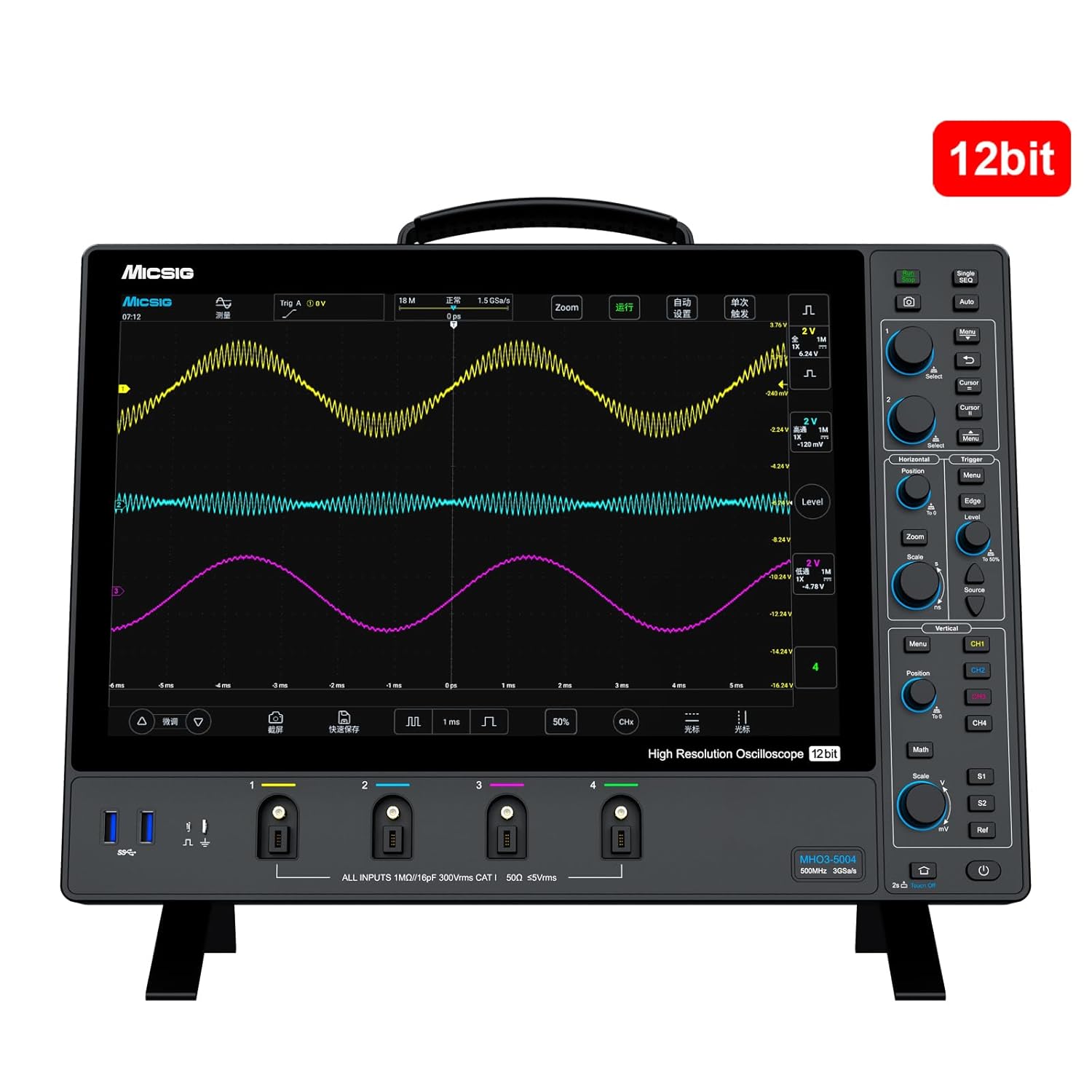
Figure 2.2: The oscilloscope highlighting its 12-bit vertical resolution capability.
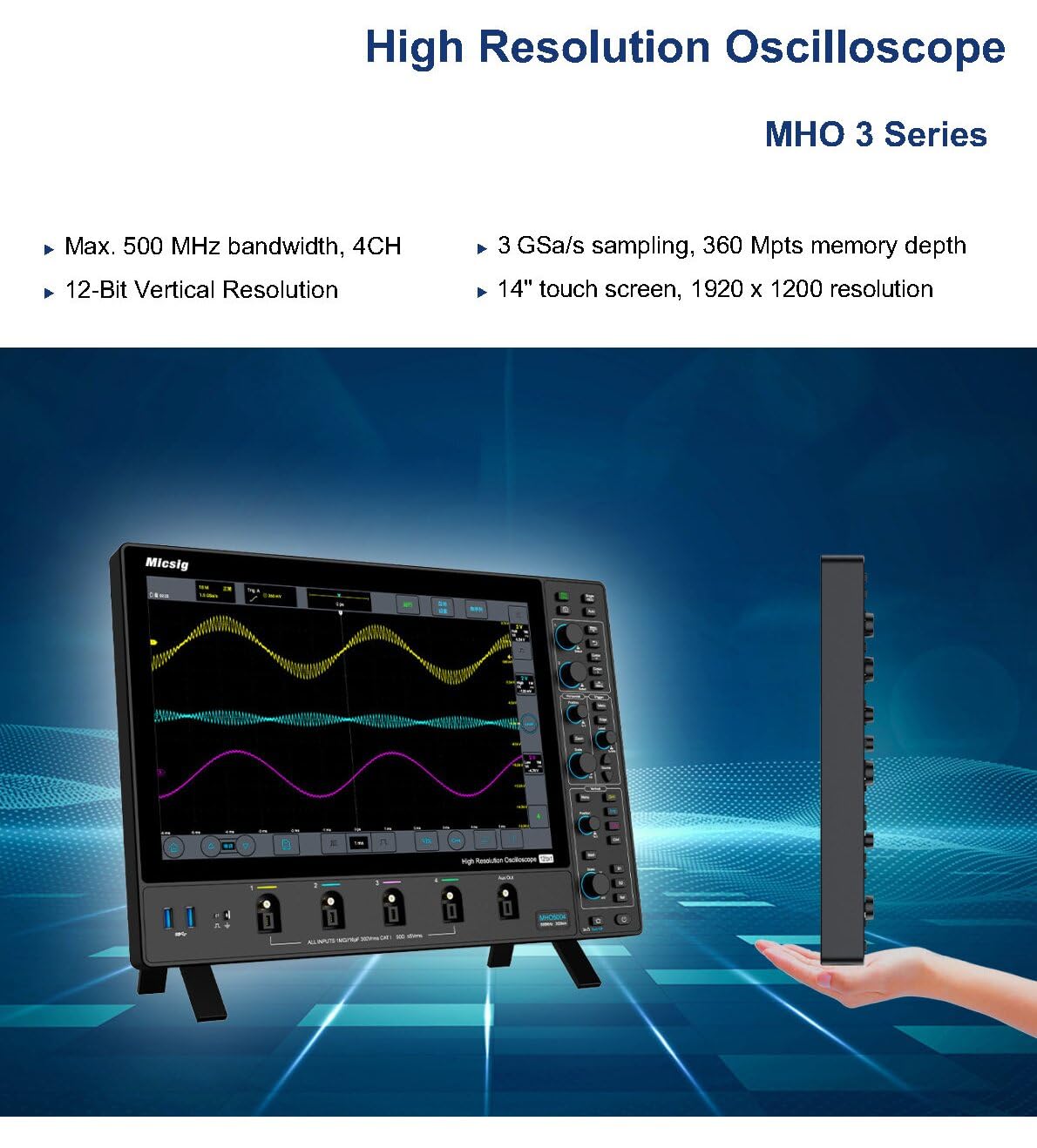
Figure 2.3: Overview of the MHO 3 Series, emphasizing its high resolution, bandwidth, sampling rate, and touch screen.

Figure 2.4: Detailed product features including waveform capture rate, anti-glare screen, and probe interface.
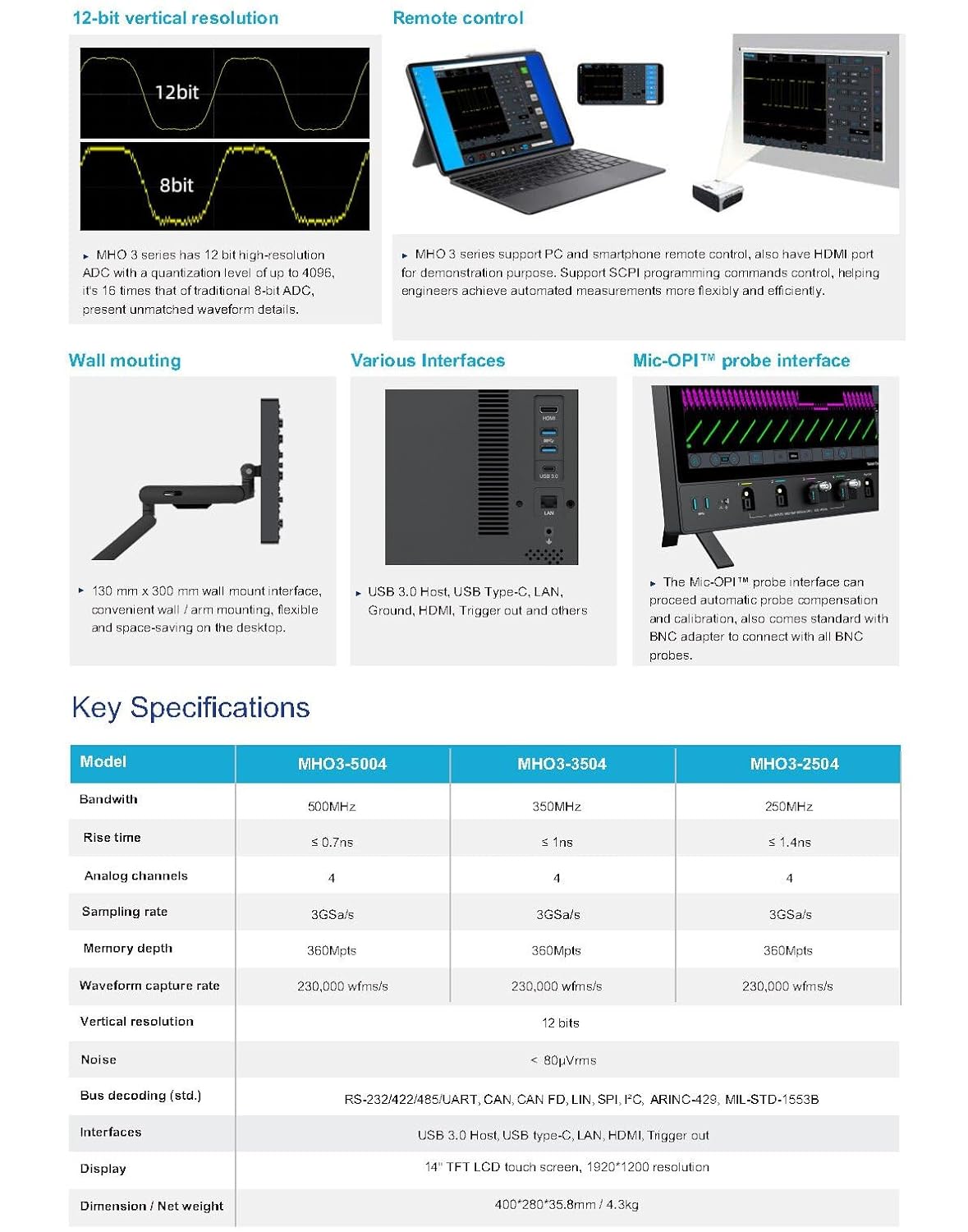
Figure 2.5: Visual representation of the 12-bit vertical resolution, remote control options, wall mounting, various interfaces, and key specifications table.
Video 2.1: An official video demonstrating the Micsig MHO 3 Series Oscilloscope's features, including its large screen, 12-bit vertical resolution, ultra-thin design, full touch and integrated button panel, Mic-OPI™ patented probe interface, and low noise floor for accurate weak signal capture.
3. Setup
- Unpacking: Carefully remove the oscilloscope and all accessories from the packaging. Verify all components listed in the packing list are present.
- Power Connection: Connect the provided power adapter to the oscilloscope's power input and then to a suitable AC power outlet.
- Initial Power On: Press the power button located on the device. The system will boot up and display the main interface.
- Probe Connection: Connect your desired probes (e.g., passive probes, active probes, current probes) to the appropriate input channels (CH1-CH4) on the front panel. Ensure a secure connection. The Mic-OPI™ interface automatically detects and configures compatible probes.
- External Connections: If needed, connect external devices using the USB 3.0 Host, USB Type-C, LAN, or HDMI ports located on the side/rear panel.
4. Operating Instructions
The MHO 3 Series oscilloscope offers both touch screen and physical button controls for flexible operation.
4.1 Basic Waveform Acquisition
- Channel Selection: Tap on the desired channel (CH1-CH4) on the screen or use the dedicated channel buttons to enable/disable channels.
- Vertical Scale (Volts/Div): Adjust the vertical scale using the touch interface or the dedicated vertical scale knob for each channel.
- Horizontal Scale (Time/Div): Adjust the horizontal time base using the horizontal scale knob or by pinching/zooming on the touch screen.
- Trigger Setup: Configure the trigger settings (Edge, Pulse, Video, etc.) to stabilize the waveform. Use the dedicated trigger controls or the touch menu.
- Run/Stop: Press the RUN/STOP button to start or stop waveform acquisition.
4.2 Advanced Features
- Measurements: Access automatic measurements (e.g., Vpp, Vrms, Frequency) through the measurement menu.
- Math Functions: Perform waveform math operations (e.g., Add, Subtract, Multiply, Divide, FFT) using the Math menu.
- Storage: Save waveforms, setups, or screenshots to internal memory or a connected USB drive. The segmented storage function allows capturing up to 10,000 segments.
- Remote Control: Utilize the mobile app or PC remote control software for remote operation via LAN or Wi-Fi (if applicable).
5. Maintenance
- Cleaning: Use a soft, dry cloth to clean the exterior of the oscilloscope. For the screen, use a screen-specific cleaning solution and a microfiber cloth. Avoid abrasive cleaners or solvents.
- Storage: When not in use, store the oscilloscope in a clean, dry environment, away from direct sunlight, extreme temperatures, and excessive dust.
- Calibration: Regular calibration by qualified personnel is recommended to maintain measurement accuracy. Refer to the manufacturer's guidelines for recommended calibration intervals.
- Software Updates: Periodically check the Micsig official website for firmware updates to ensure optimal performance and access to new features.
6. Troubleshooting
| Problem | Possible Cause | Solution |
|---|---|---|
| No power | Power cable disconnected; Power adapter faulty; Internal battery depleted (if applicable) | Check power connections; Try a different power outlet; Ensure battery is charged. |
| No waveform displayed | Channel disabled; Probe not connected correctly; Vertical/Horizontal scale incorrect; Trigger not set properly | Enable channel; Reconnect probe; Adjust scales; Adjust trigger level/mode. |
| Unstable waveform | Incorrect trigger settings; Signal noise | Adjust trigger level and mode; Check probe compensation; Use averaging or filtering functions. |
| Touch screen unresponsive | Software glitch; Screen calibration issue | Restart the device; Perform screen calibration (refer to on-screen menu). |
If the problem persists after attempting these solutions, please contact Micsig customer support for further assistance.
7. Specifications
| Feature | MHO3-2504 | MHO3-3504 | MHO3-5004 |
|---|---|---|---|
| Bandwidth | 250MHz | 350MHz | 500MHz |
| Analog Channels | 4 | ||
| Sampling Rate | 3GSa/s | ||
| Memory Depth | 360Mpts | ||
| Vertical Resolution | 12-bit | ||
| Noise Floor | < 80µVrms | ||
| Display | 14-inch TFT LCD touch screen, 1920x1200 resolution | ||
| Interfaces | USB 3.0 Host, USB Type-C, LAN, HDMI, Trigger out | ||
| Dimensions (L×W×H) | 400*280*35.8mm | ||
| Weight | Approx. 3.5 kg (7.72 lbs) | ||
8. Warranty and Support
Micsig products are backed by a manufacturer's warranty. For detailed warranty information, please refer to the warranty card included with your product or visit the official Micsig website. For technical support, troubleshooting assistance beyond this manual, or service requests, please contact Micsig customer service through their official channels.
Micsig Official Store: Visit Store
Related documentsSM-MHO2504


Ask a question about this manual
Ask about setup, troubleshooting, compatibility, parts, safety, or missing instructions. Manuals+ will review the question and use this page’s manual context to help answer it.