
1. Important Safety Information
Please read and understand all safety instructions before installing, operating, or servicing the METSEPM5560 Power Meter. Failure to follow these instructions may result in serious injury or death, and/or damage to the equipment.

Figure 1: METSEPM5560 Power Meter showing safety warnings and connection points.
- DANGER / PELIGRO: Risk of electric shock, explosion, or arc flash.
- Only qualified personnel should install, operate, and maintain this equipment.
- Always de-energize the equipment before performing any work.
- Operating temperature range: -25°C to 70°C.
- Current inputs: 1A/5A nominal, 0.05A-10A.
- Control Power: 100-480V ±10% ~, 50/60Hz < 16VA; 125-250V ±20% < 5W.
2. Product Overview
The Aoleaby METSEPM5560 is a feature-rich power and energy meter designed for precise power monitoring and energy management. It provides accurate measurements and communication capabilities for various electrical applications.
Key Features:
- Digital input and output for monitoring and control relays.
- Modbus RS485 communication port for remote monitoring.
- Precision accuracy of Class 0.2S (active power) for identifying energy savings opportunities.
- Harmonic measurement for Power Quality management.
- LCD backlight display with 128 x 128 resolution.
3. Specifications
| Specification | Value |
|---|---|
| Model Number | METSEPM5560 |
| Display Type | Digital Only, LCD backlight |
| Display Resolution | 128 x 128 |
| Phase | Single Phase |
| Measuring Energy Range | 0-999999 |
| Accuracy Class (Active Power) | 0.2S (IEC 62053-22 compliant) |
| Output Voltage | 110V, 127V, 133V, 230V, 240V |
| Operating Temperature | -10°C to +50°C |
| Supply Voltage (DC) | 125...250 V DC |
| Supply Voltage (AC) | 100...480 V AC, 45...65 Hz |
| Rated Current | 1 A, 5 A |
| Dimensions | 117.5 x 58.5 x 18 mm |
| Net Weight | 450 g (approx. 1.76 pounds) |
| Communication | Modbus RS485 |
| EAN/UPC (from packaging) | 3606480614064 |
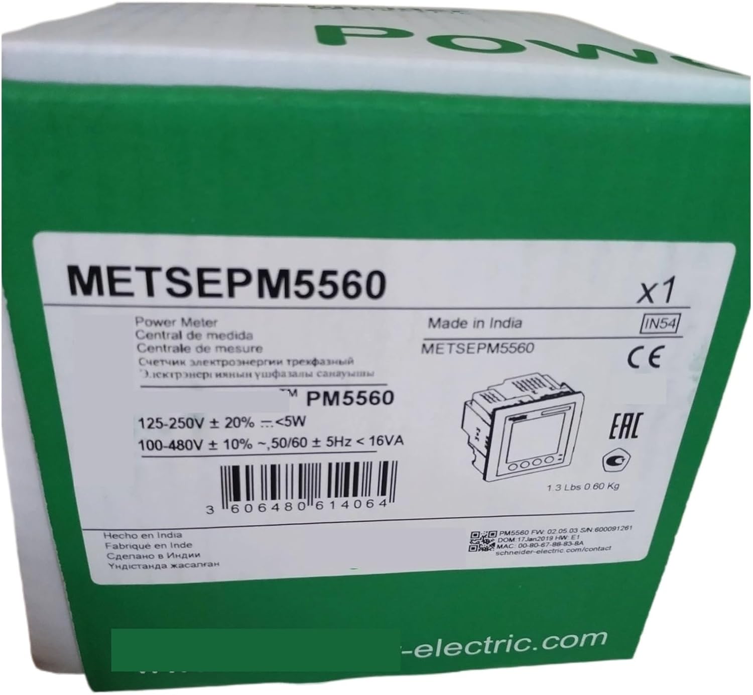
Figure 2: Product packaging for the METSEPM5560 Power Meter, showing model number and EAN/UPC.
4. Setup and Installation
Installation of the METSEPM5560 Power Meter should only be performed by qualified electricians in accordance with local electrical codes and standards. Ensure all power is disconnected before beginning installation.
4.1 Mounting
The meter is designed for panel mounting. Refer to the dimensions provided in the specifications section for appropriate panel cutout requirements. Secure the meter using the provided mounting hardware.
4.2 Wiring Connections
Carefully connect the power supply, current inputs, digital inputs, digital outputs, and RS485 communication as indicated on the device and in the wiring diagrams (refer to Figure 1 for terminal identification).
- Control Power (8, 9): Connect the main power supply (100-480V AC or 125-250V DC) to terminals (8) and (9).
- Current Inputs (I1, I2, I3, I4): Connect current transformers (CTs) to the respective current input terminals (10-17). Ensure correct polarity (S1+, S2+, S3+, S4+ and S1-, S2-, S3-, S4-).
- Digital Inputs (40-47): Connect external control signals to the digital input terminals.
- Digital Outputs (60-63): Connect relays or other control devices to the digital output terminals.
- RS-485 Communication (22, 23, 24, 25): Connect the RS-485 communication bus to terminals (22) for A, (23) for B, (24) for C (common), and (25) for shield.
- Ethernet (30, 31): Connect an Ethernet cable for network communication.
Always double-check all wiring connections before applying power to prevent damage to the meter or connected equipment.
5. Operation
Once installed and powered, the METSEPM5560 Power Meter will display measurement data on its LCD screen. The meter is designed for continuous monitoring of electrical parameters.
5.1 Display Navigation
The LCD backlight display provides clear visibility of various parameters. Use the navigation buttons (if present, not explicitly visible in images but typical for such devices) to cycle through different screens displaying voltage, current, power (active, reactive, apparent), energy consumption, power factor, frequency, and harmonic distortion.
5.2 Communication
The Modbus RS485 port allows for remote data acquisition and control. Connect the meter to a Modbus master device (e.g., PLC, SCADA system) to integrate it into a larger energy management system. Refer to the Modbus communication protocol documentation for detailed register maps and communication settings.
6. Maintenance
The METSEPM5560 Power Meter is designed for reliable operation with minimal maintenance. However, periodic checks are recommended to ensure optimal performance and longevity.
- Cleaning: Gently wipe the display and casing with a soft, dry cloth. Do not use abrasive cleaners or solvents.
- Inspection: Periodically inspect all wiring connections for tightness and signs of wear or damage.
- Environment: Ensure the operating environment remains within the specified temperature and humidity ranges.
7. Troubleshooting
If you encounter issues with your METSEPM5560 Power Meter, consider the following common troubleshooting steps:
- No Display/Power:
- Verify that the control power supply is correctly connected and within the specified voltage range.
- Check for blown fuses or tripped circuit breakers in the control power circuit.
- Incorrect Readings:
- Ensure current transformer (CT) connections are correct and polarity is observed.
- Verify that the CT ratios are correctly configured in the meter's settings (if applicable).
- Check voltage connections for proper phase and magnitude.
- Communication Issues (RS485):
- Check RS485 wiring for correct A/B polarity and secure connections.
- Verify communication settings (baud rate, parity, stop bits, slave ID) match between the meter and the master device.
- Ensure proper termination resistors are used on the RS485 bus.
If the problem persists after performing these checks, contact technical support.
8. Warranty and Support
For warranty information, please refer to the documentation provided at the time of purchase or contact your vendor. Aoleaby products are typically covered by a limited warranty against defects in materials and workmanship.
For technical support, service, or replacement parts, please contact the seller or manufacturer directly. Have your product model number (METSEPM5560) and purchase details ready when contacting support.