
1. Introduction
The Aoleaby JK BMS B1A8S10P is a smart active balance Battery Management System designed to monitor and manage 3S-8S LiFePO4, Li-ion, and LTO battery packs. It ensures optimal performance, extends battery life, and provides comprehensive protection against various electrical conditions. This manual provides essential information for the proper installation, operation, and maintenance of your BMS.
2. Product Overview
2.1 Key Features
- JK Own Development APP: Monitor battery status and adjust settings via Bluetooth communication on your smartphone (iOS/Android).
- JK Active Balance: Actively balances voltage differences between battery cells, improving battery usage efficiency up to 99% and extending battery lifespan.
- Full Functionality: Provides protection against over-charge, over-discharge, over-current, short circuit, and includes low-temperature charging cutoff.
- Safety Design: Unique design for reliable protection, crucial for battery longevity.
- Widely Applicable: Supports 12V/4S, 24V/8S, 48V/16S, 72V/24S LiFePO4 battery systems with 100A-350A max current and 0.6-2A active balance current.
2.2 Package Contents
The following items are typically included in your product package:
- JK BMS Unit
- Screws (x4)
- NTC Temperature Sensor (40cm)
- Heating Cable (16cm)
- CAN Cable (25cm)
- Switch (50cm)
- Balance Wires (70cm)

Image: Package contents of the JK BMS, showing the main unit, various cables, and accessories.
2.3 Product Features and Dimensions

Image: Front view of the JK BMS B1A8S10P-Heat-CAN, highlighting its functions (BT/RS485/Heat/CAN), 1A balance current, 4S-8S battery string compatibility, 100A charge/discharge current, dimensions (153x136x18mm), and supported battery types (Li-ion/LiFePO4/LTO).
3. Technical Specifications
The following table details the technical specifications for the B1A8S10P-Heat-CAN model:
| Parameter | Value |
|---|---|
| Supported Li-ion Strings | 3-8S |
| Supported LiFePO4 Strings | 3-8S |
| Supported LTO Strings | 7-17S |
| Temperature Sensor Supported | 14-24S |
| Balance Method | Active Balancer |
| Active Balance Current | 1A |
| Inner Resistance | 0.3mΩ |
| Continuous Discharge Current | 100A |
| Max Discharge Current (2X) | 200A |
| Overcharge Protection Current Limit | 10-20A |
| Overdischarge Protection Current Limit | 10-20A |
| Interface | RS485/CAN |
| Dimensions (L*W*H) | 153mm * 136mm * 18mm |
| Wiring Diagram Type | Same Port |
| Voltage of Single Cells | 1-5V |
| Voltage Acquisition Precision | ±5mV |
| Overcharge Protection Voltage | 1.2-4.35V ADJ |
| Overcharge Release Voltage | 1.2-4.35V ADJ |
| Overdischarge Protection Voltage | 1.2-4.35V ADJ |
| Overdischarge Release Voltage | 1.2-4.35V ADJ |
| Temperature Protection Sensors | 3 pcs |
| Short Circuit Protection | Yes |
| Coulometer | Yes |
| Bluetooth | Yes |
| APP Support | iOS / Android |
| Package Dimensions | 1.18 x 0.79 x 0.39 inches |
| Item Weight | 2.2 pounds (1000 Grams) |
Note: Specifications are subject to change without prior notice. Always refer to the latest product documentation.
4. Setup and Installation
4.1 Wiring Diagram
Carefully follow the wiring diagram to connect the BMS to your battery pack. Incorrect wiring can cause damage to the BMS, battery, or connected devices.
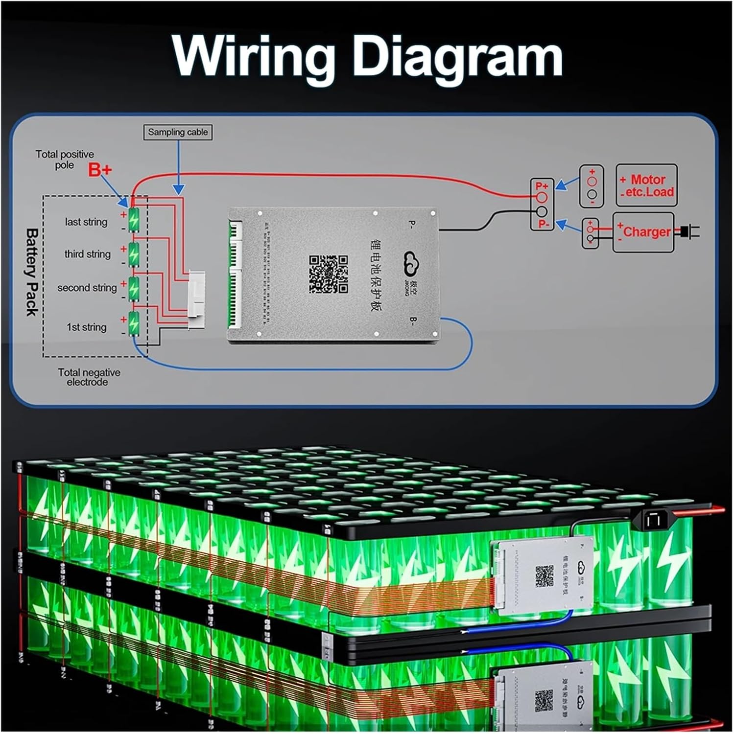
Image: Wiring diagram illustrating how to connect the BMS to a multi-string battery pack, charger, and load. The sampling cable connects to individual cell strings, while the main power cables connect to the total positive (B+) and total negative (B-) terminals. P- connects to the load/charger negative.
For detailed wiring instructions and additional resources, scan the QR code on the BMS unit or visit: http://qr17.cn/BApbC0
4.2 Installation Steps
- Prepare Battery Pack: Ensure your battery pack is assembled correctly with all cells at a similar voltage level before connecting the BMS.
- Connect Balance Wires: Connect the balance wires from each cell string to the corresponding ports on the BMS. Always connect the lowest voltage cell first, then proceed upwards.
- Connect Main Power Cables: Connect the main negative (B-) cable from the battery pack to the B- terminal on the BMS. Connect the main positive (P+) cable from the load/charger to the P+ terminal on the BMS.
- Connect Temperature Sensor: Attach the NTC temperature sensor to a central cell or area within the battery pack to monitor temperature accurately.
- Connect Optional Cables: If using, connect the heating cable, CAN cable, and switch according to your system requirements.
- Verify Connections: Double-check all connections for correctness and security before applying power.
5. Operating Instructions
5.1 Mobile Application (APP)
The JK BMS features a dedicated mobile application for real-time monitoring and configuration. The app connects via Bluetooth, allowing you to view cell voltages, total voltage, current, temperature, and adjust various protection parameters.
- Download APP: Scan the QR code on the BMS unit or refer to the product documentation to download the official JK BMS APP for iOS or Android.
- Connect via Bluetooth: Enable Bluetooth on your smartphone and open the JK BMS APP. The app should detect your BMS. Select it to establish a connection.
- Monitor and Configure: Once connected, you can monitor battery parameters, view historical data, and customize settings such as over-charge/discharge voltages, current limits, and balancing thresholds.
For APP download and detailed usage instructions, scan the QR code on the BMS unit or visit: http://qr17.cn/BApbC0
5.2 Active Balancing Function
The active balancing feature continuously monitors the voltage of each cell in your battery pack. If a voltage difference is detected, the BMS will actively transfer energy from higher voltage cells to lower voltage cells, ensuring all cells remain balanced. This process optimizes battery performance and extends its overall lifespan.
6. Application Scenarios
The Aoleaby JK BMS B1A8S10P is versatile and suitable for a wide range of applications requiring reliable battery management:
- E-bikes
- Electric Tricycles
- Low Speed Quads
- Forklifts
- Cleaning Cars
- Tourist Cars
- Industrial Drones
- Scooters
- RV Energy Storage
- Energy Storage Cabinets
- Power Banks
- Power Tools

Image: Visual representation of diverse applications where the JK Smart BMS can be utilized, from personal electric vehicles to industrial equipment and energy storage solutions.
7. Maintenance
Regular maintenance helps ensure the longevity and optimal performance of your JK BMS and battery system:
- Keep Clean: Periodically clean the BMS unit to prevent dust and debris buildup, which can affect heat dissipation.
- Check Connections: Regularly inspect all wiring connections to ensure they are secure and free from corrosion. Loose connections can lead to poor performance or damage.
- Monitor via APP: Use the mobile application to routinely check cell voltages, temperatures, and overall battery health. Address any abnormal readings promptly.
- Environmental Conditions: Ensure the BMS operates within its specified temperature and humidity ranges to prevent damage.
8. Troubleshooting
If you encounter issues with your JK BMS, consider the following basic troubleshooting steps:
- BMS Not Powering On: Verify all main power connections (B- and P+) are correctly and securely attached. Check the battery pack voltage.
- APP Not Connecting: Ensure Bluetooth is enabled on your phone and the BMS. Try restarting the APP or cycling power to the BMS. Make sure you are within Bluetooth range.
- Unusual Cell Voltage Readings: Recheck all balance wire connections to ensure they are correctly plugged into the BMS and making good contact with each cell.
- Over-Protection Triggered: If the BMS frequently triggers over-charge, over-discharge, or over-current protection, review your battery parameters in the APP. Ensure they match your battery specifications and that your load/charger is within the BMS's limits.
- Heating Function Not Working (if applicable): Check the heating cable connection and ensure the temperature sensor is properly installed. Verify heating settings in the APP.
For more complex issues or error codes displayed in the APP, consult the detailed troubleshooting guide available via the QR code link or contact technical support.
9. Warranty and Support
For warranty information, technical assistance, or to report any issues with your Aoleaby JK BMS B1A8S10P, please refer to the manufacturer's official website or contact your authorized vendor. It is recommended to retain your proof of purchase for warranty claims. Ensure to register your product if required by the manufacturer.