
1. Introduction
This manual provides instructions for the installation, operation, maintenance, and troubleshooting of the Aoleaby JK Smart BMS Battery Equalizer, model JK-BD4A24S-4P. This device is designed to protect and balance Li-ion, Lipo, and LiFePo4 battery systems ranging from 8S to 24S configurations, with current capabilities from 40A to 200A.
The JK Smart BMS features active balancing to optimize battery cell voltage, enhancing overall battery efficiency and lifespan. It includes comprehensive protection against over-charge, over-discharge, over-current, short circuits, and low-temperature charging cutoff.

Figure 1: Top view of the Aoleaby JK Smart BMS Battery Equalizer. The device features a QR code for APP download and instructions, along with connection points for P- (discharge negative) and B- (battery negative).
2. Setup and Installation
Careful installation is crucial for the safe and effective operation of your BMS. Ensure all connections are secure and correctly polarized.
2.1 Component Identification

Figure 2: Labeled diagram of the JK Smart BMS. Key components include C- (charge negative), P- (discharge negative), B- (battery negative), temperature sensor port (D1), and various balance ports (P4, P5, P6) for cell connections.
Refer to Figure 2 for the identification of key connection points and components on the BMS board:
- B-: Main negative terminal for the battery pack.
- P-: Main negative terminal for discharge (load).
- C-: Main negative terminal for charging.
- Balance Ports (P4, P5, P6): Connect to individual battery cells for voltage monitoring and balancing.
- D1: Temperature sensor port.
- QR Code: Scan to download the JK BMS APP and access additional instructions. The APP can also be accessed via http://qr17.cn/BApbC0.
2.2 Wiring Diagram
Follow the wiring diagram carefully to ensure correct connection of the BMS to your battery pack, charger, and load.
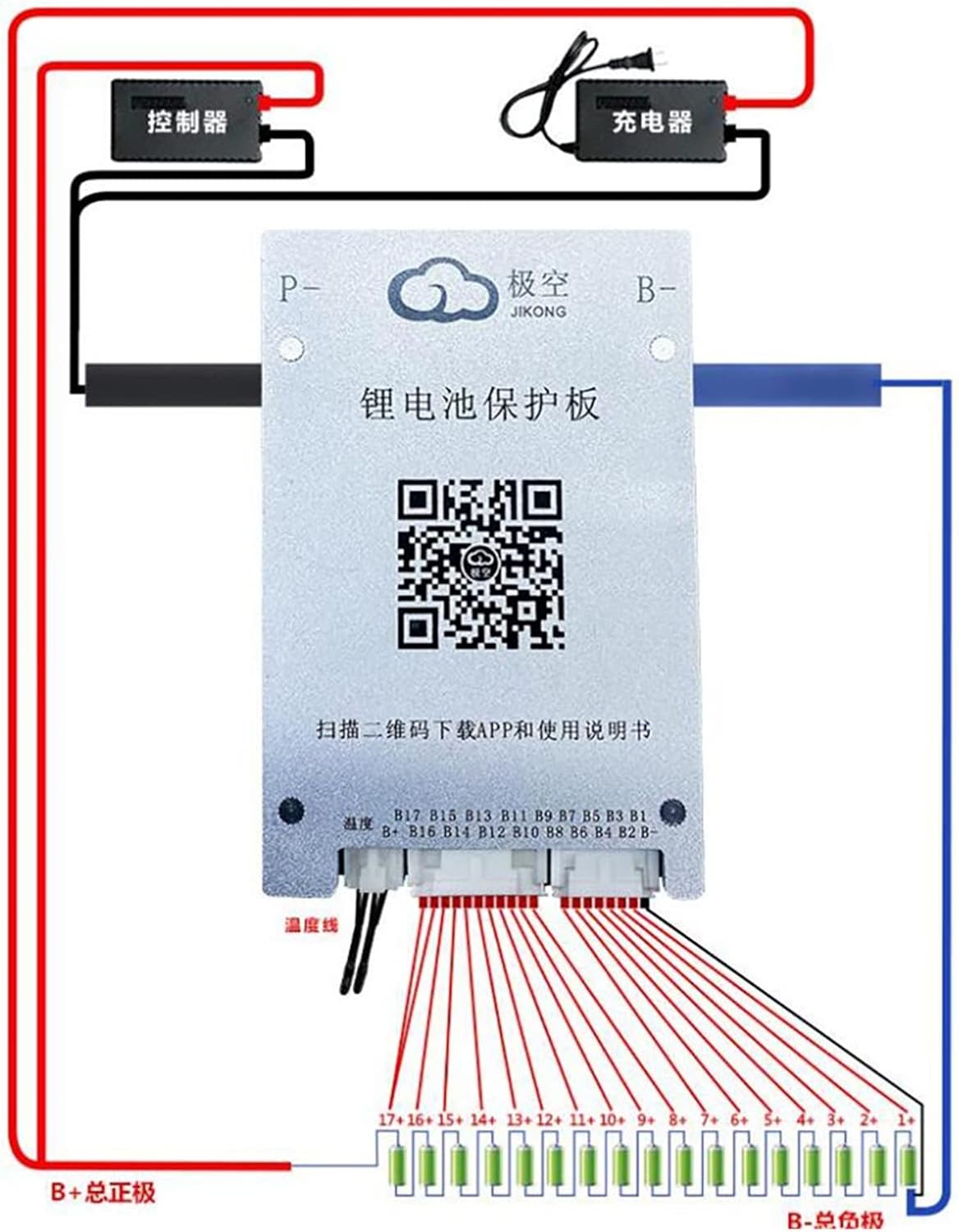
Figure 3: Comprehensive wiring diagram for the JK Smart BMS. This diagram illustrates connections for the battery pack (B+ to B-), individual cell balance wires, charger, and controller (load). Ensure B+ (total positive) and B- (total negative) are correctly identified and connected.
- Connect B-: Connect the main negative terminal of your battery pack to the B- terminal on the BMS.
- Connect Balance Wires: Connect the balance wires from your battery cells to the corresponding balance ports (P4, P5, P6) on the BMS. Ensure the wires are connected in the correct sequence (B1, B2, B3, etc.) starting from the lowest cell voltage.
- Connect P-: Connect the negative terminal of your load (controller) to the P- terminal on the BMS.
- Connect C-: Connect the negative terminal of your charger to the C- terminal on the BMS.
- Connect B+: The positive terminal of the battery pack (B+) connects directly to the positive terminals of the charger and load, bypassing the BMS.
- Temperature Sensor: Connect the temperature sensor to port D1 and place it appropriately on the battery pack for accurate temperature monitoring.
Warning: Incorrect wiring can damage the BMS, battery pack, or connected devices. Always double-check all connections before applying power.
3. Operating Instructions
Once installed, the JK Smart BMS operates automatically to protect and balance your battery. For detailed monitoring and configuration, use the dedicated mobile application.
3.1 Mobile Application (APP)
The JK BMS APP allows you to monitor the battery's real-time status, including individual cell voltages, total voltage, current, temperature, and protection status. It also provides access to various BMS settings.
- Download APP: Scan the QR code on the BMS board or visit http://qr17.cn/BApbC0 to download the official JK BMS APP.
- Bluetooth Connection: The BMS features Bluetooth (BT) communication by default. Enable Bluetooth on your mobile device and connect to the BMS via the APP.
- Monitoring: View real-time data for each cell and the overall battery pack.
- Settings: Adjust various parameters such as over-voltage, under-voltage, over-current thresholds, and balancing settings (advanced users only).
3.2 Active Balancing
The JK Smart BMS employs active balancing to equalize the voltage differences between battery cells. This process occurs automatically, improving the battery's overall efficiency and extending its service life. The active balance current for this model is typically 0.6-2A.
3.3 Protection Functions
The BMS provides comprehensive protection for your battery system:
- Over-Charge Protection: Prevents cells from being charged beyond their safe voltage limit.
- Over-Discharge Protection: Prevents cells from being discharged below their safe voltage limit.
- Over-Current Protection: Protects against excessive current during charge and discharge.
- Short Circuit Protection: Automatically disconnects the battery in case of a short circuit.
- Low Temperature Charging Cutoff: Prevents charging at temperatures that could damage the battery cells.
4. Maintenance
The Aoleaby JK Smart BMS is designed for minimal maintenance. However, periodic checks can help ensure optimal performance and longevity.
- Visual Inspection: Periodically inspect the BMS and all wiring for any signs of damage, corrosion, or loose connections.
- Cleanliness: Keep the BMS free from dust, dirt, and moisture. Use a dry, soft cloth for cleaning.
- Temperature Monitoring: Ensure the operating environment temperature remains within the recommended range for your battery type.
- Firmware Updates: Check the JK BMS APP or manufacturer's website for any available firmware updates for improved performance or new features.
Caution: Do not attempt to open or repair the BMS unit yourself. Refer to qualified personnel for service.
5. Troubleshooting
If you encounter issues with your JK Smart BMS, refer to the following common problems and solutions. For persistent issues, contact customer support.
| Problem | Possible Cause | Solution |
|---|---|---|
| BMS not powering on / No output | Incorrect wiring; Battery voltage too low; Blown fuse (if applicable) | Verify all wiring connections (B-, P-, C-). Check battery pack voltage. Inspect for any external fuses. |
| APP cannot connect to BMS | Bluetooth off; BMS out of range; APP issue | Ensure Bluetooth is enabled on your phone. Move closer to the BMS. Restart the APP or your phone. |
| Battery not balancing | Significant cell voltage difference; Balance wires disconnected | Allow time for active balancing to occur. Check balance wire connections for continuity. |
| Over-voltage/Under-voltage protection triggered | Charging/Discharging beyond limits; Faulty cell | Ensure charger/load settings are within battery limits. Check individual cell voltages via APP to identify faulty cells. |
| Over-current protection triggered | Load drawing too much current; Short circuit | Reduce load. Check for short circuits in the system. |
6. Specifications
The following specifications apply to the Aoleaby JK Smart BMS Battery Equalizer (Model: JK-BD4A24S-4P):
- Supported Battery Types: Li-ion, Lipo, LiFePo4
- Cell Series Support: 8S to 24S
- Current Rating: 40A, 80A, 100A, 150A, 200A (depending on specific model variant)
- Active Balance Current: 0.6-2A
- Communication: Bluetooth (default)
- Protection Features: Over-charge, Over-discharge, Over-current, Short Circuit, Low Temperature Charging Cutoff
- Package Dimensions: 1.18 x 0.79 x 0.39 inches
- Item Weight: 2.2 pounds
- Assembly Required: No
- Number of Pieces: 1
7. Warranty Information
Aoleaby products are manufactured to high-quality standards. For specific warranty terms and conditions, please refer to the product packaging or contact the seller directly. Typically, warranty covers defects in materials and workmanship under normal use.
Please retain your proof of purchase for any warranty claims.
8. Customer Support
For technical assistance, troubleshooting beyond this manual, or warranty inquiries, please contact your point of purchase or the manufacturer directly. Provide your product model number (JK-BD4A24S-4P) and a detailed description of the issue to facilitate support.