
1. Introduction
The VICTOR VC8045-II is a high-performance 4½ digit bench-type digital multimeter designed for precise electrical measurements. It features a large liquid crystal display and True RMS measurement capabilities, ensuring accuracy for various waveforms. This manual provides essential information for the safe and effective use of your multimeter.
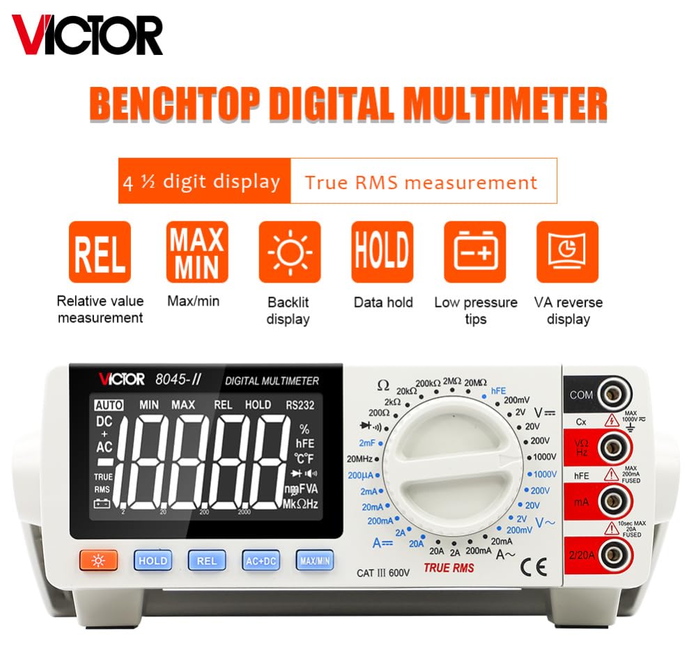
Image 1: Front view of the VICTOR VC8045-II Digital Bench Multimeter, illustrating its 4½ digit display and True RMS capability.
2. Safety Information
Always observe safety precautions when using any electrical measuring device. Failure to do so may result in electric shock, injury, or damage to the instrument.
- Ensure the multimeter is set to the correct function and range before connecting test leads to the circuit.
- Do not exceed the maximum input limits for voltage, current, or resistance.
- Inspect test leads for damage before each use. Replace if insulation is cracked or wires are exposed.
- Avoid touching exposed wiring or circuit components while taking measurements.
- Do not operate the multimeter in wet conditions or explosive atmospheres.
- Always disconnect power to the circuit before measuring resistance, capacitance, or continuity.
- Use caution when working with voltages above 60V DC or 30V AC RMS, as these pose a shock hazard.
3. Product Features
- Display: 4½-digit large LCD with backlight, maximum display 19999 counts.
- Measurement Capabilities: AC/DC Voltage, AC/DC Current, Resistance, Capacitance, Frequency, Diode Test, Continuity Test, Triode (hFE) Test.
- True RMS: Accurate measurement of AC voltage and current for non-sinusoidal waveforms.
- Special Functions: Data Hold, Max/Min Value, Relative Value Measurement, Polarity Auto-Change.
- Overload Protection: Integrated protection against over-range inputs.
- Power Supply: AC 220V/110V, 47Hz-62Hz.
- Dimensions: Approximately 260mm x 220mm x 82mm.
- Weight: Approximately 1 kg.
4. Package Contents
Verify that all items listed below are present in the package:
- VICTOR VC8045-II Digital Bench Multimeter
- Power Cable
- Test Leads (Red and Black)
- Adapters (if applicable for regional power outlets)
- Product Manual (this document)

Image 2: Contents of the VICTOR VC8045-II package, including the multimeter, power cable, adapters, test leads, and manual.
5. Panel Introduction
Familiarize yourself with the front panel controls and input terminals of the multimeter.
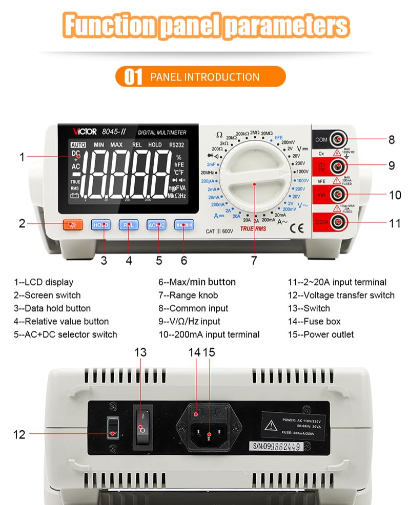
Image 3: Detailed view of the multimeter's front panel, indicating the location and function of each control and terminal.
- LCD Display: Shows measurement readings and function indicators.
- Screen Switch: Toggles display backlight.
- Data Hold Button: Freezes the current reading on the display.
- Relative Value Button: Measures the difference between a stored reference value and the current reading.
- AC+DC Selector Switch: Selects AC or DC measurement mode.
- Max/Min Button: Records and displays maximum or minimum measured values.
- Range Knob: Rotary switch to select measurement function and range.
- Common Input Terminal (COM): Negative input terminal for all measurements.
- V/Ω/Hz/hFE Input Terminal: Positive input for Voltage, Resistance, Frequency, and Triode (hFE) measurements.
- 200mA Input Terminal: Positive input for current measurements up to 200mA.
- 20A Input Terminal: Positive input for high current measurements up to 20A.
- Voltage Transfer Switch: Located on the rear panel, selects AC or DC voltage measurement.
- Switch: Main power switch, located on the rear panel.
- Fuse Box: Access point for fuse replacement, located on the rear panel.
- Power Outlet: AC power input, located on the rear panel.
6. Setup
- Power Connection: Connect the provided power cable to the Power Outlet (15) on the rear of the multimeter and then to a suitable AC power source (220V or 110V, 47Hz-62Hz).
- Power On: Flip the main Power Switch (13) to the 'ON' position. The LCD display should illuminate.
- Self-Test: The multimeter will perform a brief self-test. Wait for the display to stabilize before proceeding with measurements.
- Test Lead Connection: Insert the black test lead into the COM (Common) input terminal (8). Insert the red test lead into the appropriate positive input terminal based on the desired measurement (e.g., V/Ω/Hz/hFE for voltage, resistance, etc., 200mA for low current, or 20A for high current).
7. Operating Instructions
This section outlines the procedures for common measurements. Always ensure the multimeter is set to the correct function and range before connecting to a circuit.
7.1. Measuring DC Voltage (DCV)
- Set the Range Knob (7) to the desired DCV range (e.g., 2V, 20V, 200V, 1000V). If the voltage is unknown, start with the highest range and decrease as needed.
- Connect the black test lead to the COM terminal (8) and the red test lead to the V/Ω/Hz/hFE terminal (9).
- Connect the test leads in parallel across the DC voltage source or component to be measured.
- Read the voltage value on the LCD display (1).
7.2. Measuring AC Voltage (ACV)
- Set the Range Knob (7) to the desired ACV range (e.g., 2V, 20V, 200V, 1000V).
- Ensure the AC+DC Selector Switch (5) is set to AC.
- Connect the black test lead to the COM terminal (8) and the red test lead to the V/Ω/Hz/hFE terminal (9).
- Connect the test leads in parallel across the AC voltage source or component to be measured.
- Read the voltage value on the LCD display (1). The multimeter will display the True RMS value.
7.3. Measuring DC Current (DCA)
Caution: Always connect the multimeter in series with the circuit when measuring current. Disconnect power before connecting the multimeter.
- Turn off power to the circuit.
- Set the Range Knob (7) to the desired DCA range (e.g., 200uA, 2mA, 20mA, 200mA, 2A, 20A).
- Connect the black test lead to the COM terminal (8).
- For currents up to 200mA, connect the red test lead to the 200mA input terminal (10). For currents up to 20A, connect the red test lead to the 20A input terminal (11).
- Break the circuit and connect the multimeter in series.
- Restore power to the circuit.
- Read the current value on the LCD display (1).
- Turn off power, disconnect the multimeter, and restore the circuit.
7.4. Measuring Resistance (Ω)
Caution: Ensure the circuit is de-energized and all capacitors are discharged before measuring resistance.
- Turn off power to the circuit.
- Set the Range Knob (7) to the desired Ω range (e.g., 200Ω, 2kΩ, 20kΩ, 200kΩ, 2MΩ, 20MΩ).
- Connect the black test lead to the COM terminal (8) and the red test lead to the V/Ω/Hz/hFE terminal (9).
- Connect the test leads across the component whose resistance is to be measured.
- Read the resistance value on the LCD display (1).
7.5. Diode Test
- Set the Range Knob (7) to the Diode Test function (usually indicated by a diode symbol).
- Connect the black test lead to the COM terminal (8) and the red test lead to the V/Ω/Hz/hFE terminal (9).
- Connect the red test lead to the anode and the black test lead to the cathode of the diode. The display will show the forward voltage drop.
- Reverse the test leads. The display should show "OL" (Open Loop) for a good diode.
7.6. Continuity Test
- Set the Range Knob (7) to the Continuity Test function (usually indicated by a buzzer symbol).
- Connect the black test lead to the COM terminal (8) and the red test lead to the V/Ω/Hz/hFE terminal (9).
- Touch the test leads across the component or wire to be tested.
- If continuity exists (resistance below a certain threshold), the buzzer will sound, and the display will show a low resistance value.
7.7. Measuring Frequency (Hz)
- Set the Range Knob (7) to the Frequency (Hz) function.
- Connect the black test lead to the COM terminal (8) and the red test lead to the V/Ω/Hz/hFE terminal (9).
- Connect the test leads in parallel across the signal source.
- Read the frequency value on the LCD display (1).
7.8. Measuring Capacitance (CAP)
Caution: Ensure capacitors are fully discharged before measuring capacitance to prevent damage to the multimeter.
- Turn off power to the circuit and discharge the capacitor.
- Set the Range Knob (7) to the Capacitance (CAP) function.
- Connect the black test lead to the COM terminal (8) and the red test lead to the V/Ω/Hz/hFE terminal (9).
- Connect the test leads across the capacitor.
- Read the capacitance value on the LCD display (1).
7.9. Triode (hFE) Test
- Set the Range Knob (7) to the hFE function.
- Insert the transistor leads into the appropriate hFE test sockets (NPN or PNP) on the front panel.
- Read the hFE value on the LCD display (1).
8. Maintenance
- Cleaning: Wipe the multimeter with a damp cloth and mild detergent. Do not use abrasives or solvents.
- Storage: Store the instrument in a dry, dust-free environment away from direct sunlight and extreme temperatures.
- Fuse Replacement: If the current measurement function fails, the fuse may need replacement. Refer to the fuse box (14) for access. Ensure to replace with a fuse of the correct type and rating as specified in the specifications.
- Calibration: For continued accuracy, periodic calibration by qualified personnel is recommended.
9. Troubleshooting
| Problem | Possible Cause | Solution |
|---|---|---|
| No display when powered on. | No power, faulty power cable, or internal issue. | Check power cable connection and wall outlet. Ensure power switch is ON. |
| "OL" or "1" displayed during measurement. | Over-range, open circuit, or incorrect function/range selection. | Select a higher range. Check for open circuits. Verify correct function. |
| Inaccurate readings. | Incorrect range, poor test lead connection, or uncalibrated unit. | Select appropriate range. Ensure secure test lead connections. Consider calibration. |
| Current measurement not working. | Blown fuse. | Replace the fuse with the correct type and rating. |
10. Specifications
Detailed technical specifications for the VICTOR VC8045-II Digital Bench Multimeter.
General Specifications:
- Display: 4½-digit LCD, Max. 19999 counts
- Operation Method: Manual Range
- Power Supply: AC 220V/110V, 47Hz-62Hz
- Dimensions: 260mm (L) x 220mm (W) x 82mm (H)
- Weight: Approx. 1 kg
- Material: Acrylonitrile Butadiene Styrene (ABS)
- Certifications: CE, RoHS, UL
- Operating Temperature: Up to 60°C
Measurement Specifications:
| Function | Range | Basic Accuracy | Resolution |
|---|---|---|---|
| DC Voltage | 200mV / 2V / 20V / 200V / 1000V | ±(0.05%+5) for 200mV ±(0.1%+5) for 1000V | 10uV / 100uV / 1mV / 10mV / 100mV |
| AC Voltage (True RMS) | 2V / 20V / 200V / 1000V | 40Hz-1kHz: ±(0.5%+30) 1kHz-10kHz: ±(2%+30) 10kHz-20kHz: ±(3%+60) 20kHz-50kHz: ±(10%+250) | 100uV / 1mV / 10mV / 100mV |
| DC Current | 200uA / 2mA / 20mA / 200mA / 2A / 20A | ±(0.35%+10) for 200uA ±(0.8%+10) for 2A ±(2.0%+15) for 20A | 0.01uA / 0.1uA / 1uA / 10uA / 100uA / 1mA |
| AC Current (True RMS) | 20mA / 200mA / 2A / 20A | ±(0.8%+80) for 20mA ±(2.5%+35) for 20A | 1uA / 10uA / 100uA / 1mA |
| Resistance | 200Ω / 2kΩ / 20kΩ / 200kΩ / 2MΩ / 20MΩ | ±(0.5%+30) for 200Ω ±(0.5%+40) for 2MΩ ±(0.6%+50) for 20MΩ | 0.01Ω / 0.1Ω / 1Ω / 10Ω / 100Ω / 1kΩ |
| Frequency | 200Hz / 2kHz / 20kHz / 200kHz / 2MHz / 20MHz | ±(0.1%+3) | 0.01Hz / 0.1Hz / 1Hz / 10Hz / 100Hz / 1kHz |
| Capacitance | 20nF / 200nF / 2uF / 20uF / 200uF / 2000uF | ±(3.5%+20) for 20nF ±(5%+30) for 2000uF | 1pF / 10pF / 100pF / 1nF / 10nF / 100nF |
Image 4: Table detailing the basic function ranges, accuracy, and resolution for various measurements.

Special Functions:
- Diode Test: Yes
- Triode Test (hFE): Yes
- Continuity Buzzer: Yes
- Overload Protection: Yes (250V rms for certain functions)
- ACV Frequency Response: 50kHz
Image 5: Table summarizing special functions and general operational characteristics.


