
1. Introduction
This manual provides essential information for the safe and efficient installation, operation, and maintenance of your doinal 2000W 48V Brushless Motor Kit. Please read all instructions carefully before use to ensure proper function and longevity of the product. This kit is designed for electric scooter conversion, mid-drive motor applications, electric motorcycles, and electric go-karts.

Figure 1: Examples of applications for the doinal 2000W 48V Brushless Motor Kit.
2. Product Overview
The doinal 2000W 48V Brushless Motor Kit includes a high-performance brushless DC motor, a sine wave controller, a half-twist throttle with voltage display, a T8F sprocket, and a T8F chain. This kit is engineered for efficiency and durability.
2.1 Key Components
- 48V 2000W Brushless Motor: Features a pure copper core, high efficiency, and high-temperature resistance.
- 45A Sine Wave Controller: Equipped with a self-learning function and is programmable.
- Half Twist Throttle: Includes an integrated voltage display for monitoring battery status.
- T8F Sprocket and Chain: Essential for power transmission.

Figure 2: Motor with detachable heat sink housing and key specifications.

Figure 3: Internal view of the motor showing copper core.

Figure 4: Motor with heat dissipation holes.

Figure 5: Sine Wave Controller.
2.2 Product Video
Video 1: Overview of the Electric Brushless Motor Kit, demonstrating components and basic connections.
3. Safety Information
Always prioritize safety when working with electrical components and machinery. Failure to follow safety guidelines can result in injury or damage to the product.
- Ensure all power is disconnected before performing any installation, maintenance, or troubleshooting.
- Wear appropriate personal protective equipment (PPE), including safety glasses and gloves.
- Verify all wiring connections are secure and correctly insulated to prevent short circuits.
- Do not operate the motor kit in wet conditions unless all components are specifically rated for such environments.
- Keep hands and loose clothing away from moving parts, such as the chain and sprocket, during operation.
- This motor kit is intended for off-road use only. Always check and comply with local laws and regulations regarding electric vehicle use.
4. Setup and Installation
Careful installation is crucial for the optimal performance and safety of your motor kit. Follow these steps for proper setup.
4.1 Motor Installation
- The motor features installation holes suitable for M6 screws. Ensure a secure mounting to your vehicle's frame.
- Mount the motor in a location that allows for proper chain alignment and heat dissipation.

Figure 6: Motor installation hole for M6 screws (95mm diameter).
4.2 Sprocket and Chain Installation
- Install the T8F 54T sprocket onto the motor shaft.
- Connect the T8F chain, ensuring proper tension.
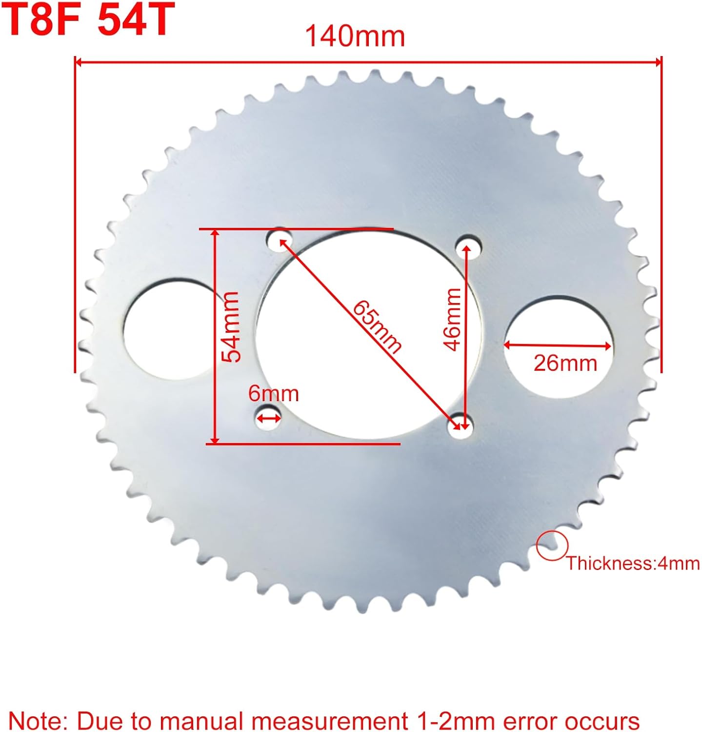
Figure 7: T8F 54T Sprocket dimensions.
4.3 Wiring the Controller and Components
Refer to the following diagrams for correct wiring connections. Ensure all connections are tight and properly insulated.
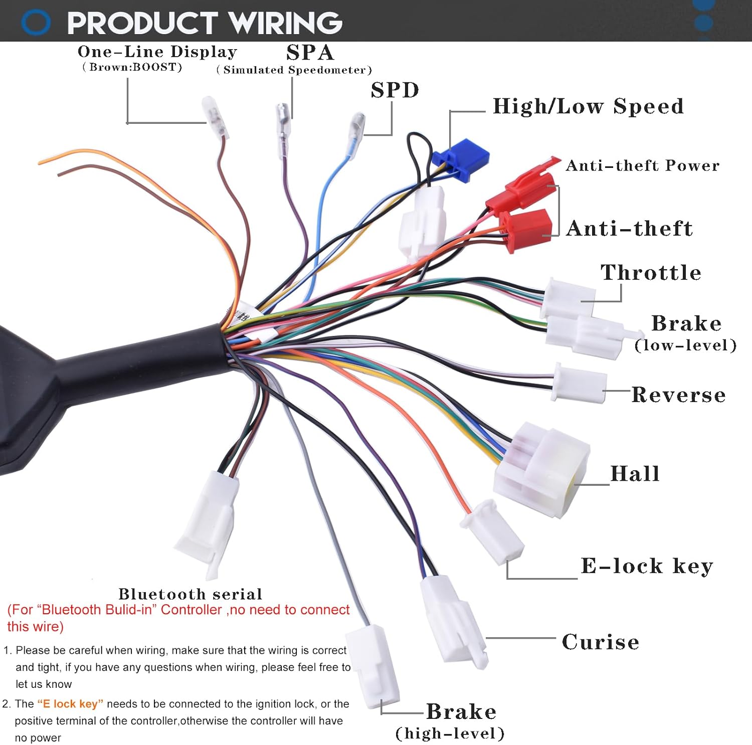
Figure 8: Overall Product Wiring Diagram.
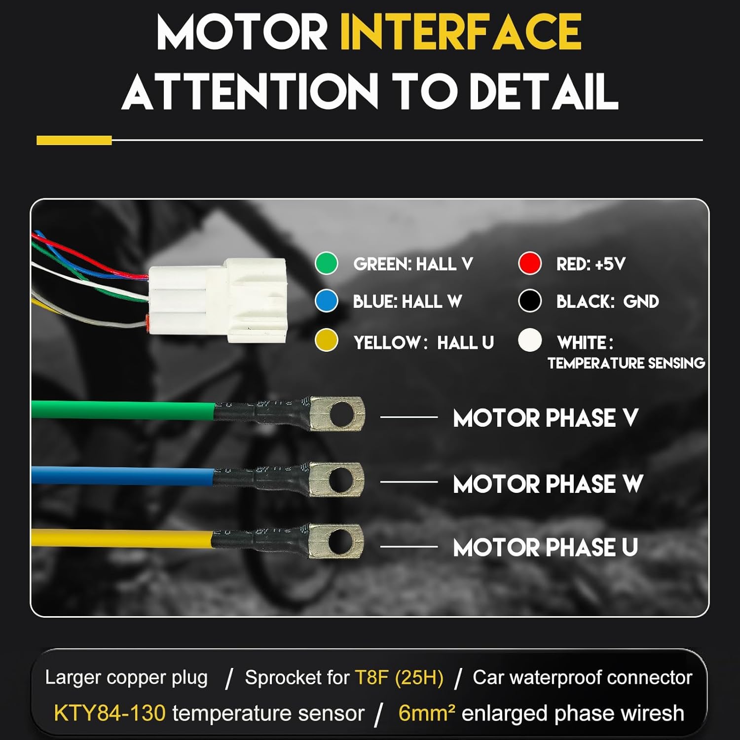
Figure 9: Motor Interface Wiring Details.

Figure 10: Hall Sensor Wiring.

Figure 11: Wiring for Anti-Theft, P/Cruise, High/Low Speed, Throttle, Reverse, and Brake.
E-Lock (Power Lock) Connection
When using the controller, you must connect the "E Lock" wire to the positive terminal of the controller or the ignition lock. Failure to do so will prevent the controller from receiving power and operating normally.

Figure 12: E-Lock (Power Lock) Wiring.
Bluetooth Serial Connection
For controllers with built-in Bluetooth, there is no need to connect a separate Bluetooth serial wire. The controller can be directly connected to the Fardrive application for parameter settings.
5. Operating Instructions
Once installed, follow these instructions to operate your doinal motor kit.
5.1 Initial Power-Up
- Ensure all connections are secure before turning on the power.
- Turn the ignition key (if installed) to the ON position.
- The voltage display on the throttle will show the current battery voltage.
5.2 Throttle Operation
The half-twist throttle controls the motor speed. Twist the throttle gently to accelerate. Release the throttle to decelerate.
5.3 Fardrive Application Usage
The Fardrive application allows you to monitor motor status and adjust controller parameters. The motor's status, including speed and current, is clearly visible within the app.

Figure 13: Fardrive App Interface for monitoring and settings.
Motor Direction Adjustment
The motor's rotation direction (clockwise or counter-clockwise) can be changed by adjusting the corresponding setting (0 or 1) in the Fardrive application.
Controller Parameter Tuning
The controller comes with pre-set parameters. If tuning is required, refer to the Fardrive application's detailed instructions or consult a professional. Incorrect tuning may affect controller performance.

Figure 14: Fardrive App Download Information.
6. Maintenance
Regular maintenance ensures the longevity and reliable operation of your motor kit.
- Wiring Inspection: Regularly check the wiring of the controller and motor to ensure all connections are tight and free from corrosion or damage. Loose connections can lead to overheating or short circuits.
- Cleaning: Keep the motor and controller free from dirt, dust, and moisture. Use a dry cloth for cleaning.
- Heat Dissipation: Ensure the motor's heat sink housing and any ventilation areas are clear of obstructions to allow for efficient heat dissipation.
- Sprocket and Chain: Inspect the sprocket and chain for wear and proper tension. Lubricate the chain as needed.
7. Troubleshooting
This section provides guidance for common issues. For complex problems, contact customer support.
7.1 Beep Alarm Codes
The controller may emit beep alarms to indicate specific issues. Refer to the table below for common beep patterns and their meanings.

Figure 15: Beep Alarm Codes and Reasons.
- Normal Startup: One short beep.
- Continuous Beep: Indicates brake and throttle are engaged simultaneously. Release both to stop the beep.
- Two Short Beeps, One Long Beep (repeated): Controller is in self-learning mode. Proceed with self-learning operations.
- Two Short Beeps, Brief Pause, One Short Beep (repeated): Controller program verification failure. An upgrade may be required.
- Four Short Beeps, One Long Beep, Five Short Beeps (repeated): Indicates an incompatible program. Verify the program matches the controller's model.
7.2 General Troubleshooting Tips
- No Power: Check battery connections, E-Lock wiring, and ensure the ignition is on.
- Motor Not Spinning: Verify throttle connection, Hall sensor wiring, and check for any beep alarms.
- Irregular Operation: Inspect all wiring for loose connections. If using the Fardrive app, check motor status and parameters.
8. Specifications
| Feature | Specification |
|---|---|
| Motor Type | Brushless DC Motor |
| Rated Voltage | 48V |
| Rated Power | 2000W |
| Rated Speed | 4300 RPM |
| Max Speed | 5400 RPM |
| Rated Current | 42A |
| Torque | 6.9 N.M |
| Controller Max DC Current | 45A |
| Controller Phase Current | 240A |
| Waterproof Grade | IP57 (Motor), IP67 (Controller) |
| Motor Dimensions | 5.3"W x 4"H (approx. 135mm x 105mm) |
| Material | Aluminum, Copper |
| Item Weight | 12.1 pounds (approx. 5.5 kg) |
9. Warranty Information
For specific warranty details regarding your doinal 2000W 48V Brushless Motor Kit, please refer to the warranty documentation provided at the time of purchase or contact the seller directly. Keep your proof of purchase for any warranty claims.
10. Support
If you encounter any issues not covered in this manual or require further assistance, please contact the seller or manufacturer's customer support. Provide your product model number and a detailed description of the issue for efficient service.