
1. Introduction
This manual provides essential information for the proper installation, operation, and maintenance of the DWFSKZKV DSE4520 Generator Controller. The DSE4520 is a compact automatic failover module designed to offer a comprehensive set of features for generator control applications. Please read this manual thoroughly before attempting to install or operate the device.
2. Product Overview
The DSE4520 controller is engineered to manage generator operations, including monitoring engine parameters, protecting the engine, and providing automatic start/stop functionality. Its compact design integrates various features for efficient power management.
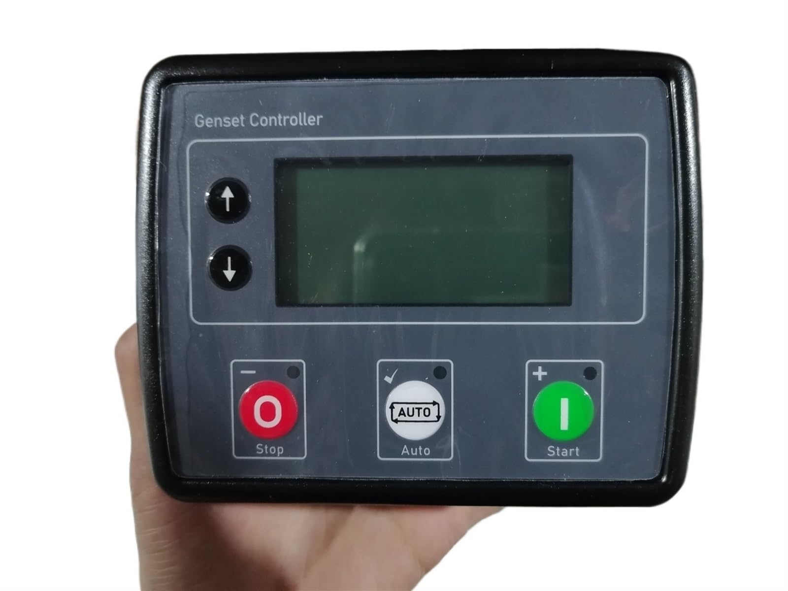
Figure 1: DWFSKZKV DSE4520 Generator Controller. This image displays the top-down view of the controller, highlighting its various terminal connections and printed specifications. Key details visible include DC Supply, DC Outputs, DC Inputs, AC Voltage Inputs, AC Current Inputs, Charge Alternator, Magnetic Pickup, and Comms Port specifications. The model number '4520 MKII BYV' and part number '529425' are also visible on the label.
3. Setup and Installation
3.1 Power Supply Connection
Connect the DC power supply to the designated terminals. Ensure the supply voltage is within the specified range to prevent damage to the unit.
- DC Supply: 8V to 35V, 0.5A Max.
3.2 Input/Output Connections
Carefully connect all input and output wiring according to your system's requirements. Refer to the terminal numbering on the device for correct connections.
- DC Outputs: 30V, 5A (terminals 3-4), 2A (terminals 6-9).
- DC Inputs: 30V Max.
- AC Voltage Inputs: 600Vac, 50/60Hz, 1-3 phase.
- AC Current Inputs: 5A, 50/60Hz, 1-3 phase.
3.3 Charge Alternator and Magnetic Pickup
Connect the charge alternator and magnetic pickup as per the system design. These connections are crucial for engine charging and speed sensing.
- Charge Alternator: 30V, 2.5W Max.
- Magnetic Pickup: 70V, 10kHz Max.
3.4 Communications Port
The communications port allows for configuration and monitoring. Ensure the connected device adheres to the specified voltage.
- Comms Port: 5V Max.
4. Operation
Once installed, the DSE4520 controller can be configured and operated through its interface. The module is designed for automatic operation, monitoring the power supply and initiating generator start/stop sequences as required.
- Power On: Apply DC power to the controller. The unit will perform a self-test and initialize.
- Monitoring: The controller continuously monitors critical parameters of the generator and mains supply.
- Automatic Start/Stop: Based on configured settings, the controller will automatically start the generator upon mains failure and stop it upon mains return.
- Manual Control: Manual start and stop functions are typically available for testing and maintenance. Refer to the on-screen menu for specific options.
5. Maintenance
Regular maintenance ensures the longevity and reliable operation of your DSE4520 controller.
- Cleaning: Keep the controller clean and free from dust and debris. Use a soft, dry cloth for cleaning. Do not use abrasive cleaners or solvents.
- Connection Checks: Periodically inspect all wiring connections for tightness and signs of corrosion. Loose connections can lead to intermittent operation or failure.
- Environmental Conditions: Ensure the operating environment remains within the specified temperature and humidity ranges.
6. Troubleshooting
This section provides guidance on common issues you might encounter with the DSE4520 controller.
| Problem | Possible Cause | Solution |
|---|---|---|
| Controller does not power on | No DC supply; Incorrect voltage; Loose connections | Check DC power source; Verify voltage (8-35V); Inspect wiring. |
| Generator fails to start | Low fuel; Low battery; Engine fault; Incorrect configuration | Check fuel level; Check battery voltage; Investigate engine fault codes; Review controller settings. |
| Inaccurate readings | Sensor fault; Incorrect wiring; Calibration issue | Check sensor connections; Verify wiring; Consult technical support for calibration. |
For issues not listed here, or if solutions do not resolve the problem, please contact technical support.
7. Technical Specifications
The following specifications apply to the DWFSKZKV DSE4520 Generator Controller:
| Parameter | Specification |
|---|---|
| DC Power Continuous Rated Voltage | 8V to 35V |
| Separate Output Survival | 50 ms at 0 V (supply at least 10 V before dropout, returns to 5 V) |
| Maximum Operating Current | 85 mA at 12 V, 96 mA at 24 V |
| Maximum Standby Current | 51 mA at 12 V, 47 mA at 24 V |
| Sleep Current | 35 mA at 12 V, 32 mA at 24 V |
| Maximum Deep Sleep Current | <10 uA at 12 V |
| DC Outputs | 30V, 5A (terminals 3-4); 2A (terminals 6-9) |
| DC Inputs | 30V Max |
| AC Voltage Inputs | 600Vac, 50/60Hz, 1-3 phase |
| AC Current Inputs | 5A, 50/60Hz, 1-3 phase |
| Charge Alternator | 30V, 2.5W Max |
| Magnetic Pickup | 70V, 10kHz Max |
| Comms Port | 5V Max |
| Package Dimensions | 1.18 x 0.79 x 0.39 inches |
| Item Weight | 1.76 ounces |
8. Warranty Information
This product is covered by a standard manufacturer's warranty against defects in materials and workmanship. The warranty period typically begins from the date of purchase. Please retain your proof of purchase for any warranty claims. The warranty does not cover damage caused by improper installation, misuse, unauthorized modifications, or external factors such as power surges or environmental conditions outside the specified operating range. For detailed warranty terms and conditions, please refer to the documentation provided at the time of purchase or contact the seller.
9. Support
For technical assistance, troubleshooting beyond this manual, or inquiries regarding your DWFSKZKV DSE4520 Generator Controller, please contact your supplier or the manufacturer's customer support. When contacting support, please have your product model number (DSE4520) and any relevant purchase information ready.
Part Number: 529425