1. Introduction
The Mastech MS8233B is a compact, handheld digital multimeter designed for measuring AC/DC voltage, DC current, resistance, diode, continuity, and temperature. It features a 2000-count display, data hold function, and low battery indication, making it suitable for various electrical testing applications in domestic and electronics environments.
2. Safety Information
To ensure safe operation and service of the meter, please read this manual thoroughly before use. Failure to observe safety warnings can result in severe injury or death.
- Always ensure the meter is in good working condition before use.
- Do not apply more than the rated voltage, which is 600V CAT III.
- Use caution when working with voltages above 30V AC RMS, 42V peak, or 60V DC, as these pose a shock hazard.
- Always disconnect the test leads from the circuit before changing functions.
- Replace the battery immediately when the low battery indicator appears.
- Do not operate the meter if the battery cover is not properly closed.
- Adhere to local and national safety codes.
3. Product Overview
The Mastech MS8233B Digital Multimeter features a clear display, a rotary function switch, and dedicated input jacks for various measurements.

Figure 3.1: Front view of the Mastech MS8233B Digital Multimeter. This image displays the LCD screen, rotary function switch, input jacks, and control buttons.
3.1 Components
- LCD Display: Shows measurement readings, units, and function indicators.
- Function Rotary Switch: Used to select the desired measurement function (e.g., V~, V-, A-, Ω, Diode, Continuity, Temp).
- HOLD Button: Freezes the current reading on the display.
- Backlight Button: Activates the display backlight for improved visibility in low-light conditions.
- VΩmA Input Jack: Positive input for voltage, resistance, diode, continuity, and current measurements up to 200mA.
- COM Input Jack: Common (negative) input for all measurements.
- 10A Input Jack: Positive input for high current measurements (up to 10A).
4. Setup
4.1 Battery Installation
The MS8233B requires 2 LR44 batteries for operation. Ensure the batteries are installed correctly before first use or when replacing them.
- Turn off the multimeter and disconnect all test leads.
- Locate the battery compartment on the back of the meter.
- Use a screwdriver to open the battery compartment cover.
- Insert the 2 LR44 batteries, observing the correct polarity (+ and -).
- Replace the battery compartment cover and secure it with the screw.
5. Operating Instructions
Before taking any measurements, ensure the test leads are properly connected to the meter and the circuit under test.
5.1 General Operation
- Turn the rotary switch from the "OFF" position to the desired measurement function.
- Connect the test leads to the appropriate input jacks and the circuit.
- Read the measurement value on the LCD display.
- To turn off the meter, rotate the switch back to the "OFF" position.
5.2 DC Voltage Measurement (V-)
- Set the rotary switch to the desired DC Voltage range (e.g., 200mV, 2V, 20V, 200V, 600V).
- Connect the red test lead to the VΩmA jack and the black test lead to the COM jack.
- Connect the test leads across the component or circuit to be measured.
5.3 AC Voltage Measurement (V~)
- Set the rotary switch to the desired AC Voltage range (e.g., 200V, 600V).
- Connect the red test lead to the VΩmA jack and the black test lead to the COM jack.
- Connect the test leads across the AC voltage source.
5.4 DC Current Measurement (A-)
- Set the rotary switch to the desired DC Current range (e.g., 200µA, 2mA, 20mA, 200mA, 10A).
- For currents up to 200mA, connect the red test lead to the VΩmA jack. For currents up to 10A, connect the red test lead to the 10A jack. Always connect the black test lead to the COM jack.
- Connect the meter in series with the circuit to measure the current.
- Caution: Do not attempt to measure currents exceeding 200mA through the VΩmA jack or 10A through the 10A jack.
5.5 Resistance Measurement (Ω)
- Set the rotary switch to the desired Resistance range (e.g., 200Ω, 2kΩ, 20kΩ, 200kΩ, 2MΩ).
- Connect the red test lead to the VΩmA jack and the black test lead to the COM jack.
- Connect the test leads across the resistor or component to be measured. Ensure the circuit is de-energized.
5.6 Diode Test
- Set the rotary switch to the Diode symbol.
- Connect the red test lead to the VΩmA jack and the black test lead to the COM jack.
- Connect the red test lead to the anode and the black test lead to the cathode of the diode. The display will show the forward voltage drop.
- Reverse the leads. An open circuit (OL) reading indicates a good diode. A reading in both directions or no reading indicates a faulty diode.
5.7 Continuity Test
- Set the rotary switch to the Continuity symbol.
- Connect the red test lead to the VΩmA jack and the black test lead to the COM jack.
- Connect the test leads across the circuit or component. If the resistance is less than approximately 60Ω, the buzzer will sound, indicating continuity.
5.8 Temperature Measurement
While the product title mentions temperature, the MS8233B model's detailed specifications do not explicitly list a temperature function. If your specific unit includes this feature, typically you would:
- Set the rotary switch to the Temperature function (usually marked with °C or °F).
- Connect a K-type thermocouple (if included) to the VΩmA and COM jacks, observing polarity.
- Place the thermocouple probe at the point where temperature needs to be measured.
5.9 Data Hold Function
- Press the "HOLD" button to freeze the current reading on the display.
- Press the "HOLD" button again to release the reading and resume live measurements.
5.10 Backlight Function
- Press the backlight button (often marked with a sun symbol) to turn on the display backlight.
- Press the button again to turn off the backlight.
6. Maintenance
6.1 Battery Replacement
When the low battery indicator appears on the display, replace the batteries as described in Section 4.1. Always use 2 new LR44 batteries.
6.2 Cleaning
Wipe the case with a damp cloth and mild detergent. Do not use abrasives or solvents. Ensure the meter is completely dry before use.
7. Troubleshooting
- No Display/Faint Display: Check battery installation and charge. Replace batteries if necessary.
- "OL" or "1" on Display: Indicates an over-range condition or open circuit. Select a higher range or check connections.
- Incorrect Readings: Ensure correct function selection, proper lead connection, and that the circuit is de-energized for resistance/diode tests.
- No Continuity Buzzer: Check if the resistance is above 60Ω or if the function is correctly selected.
8. Specifications
The following table outlines the technical specifications for the Mastech MS8233B Digital Multimeter.
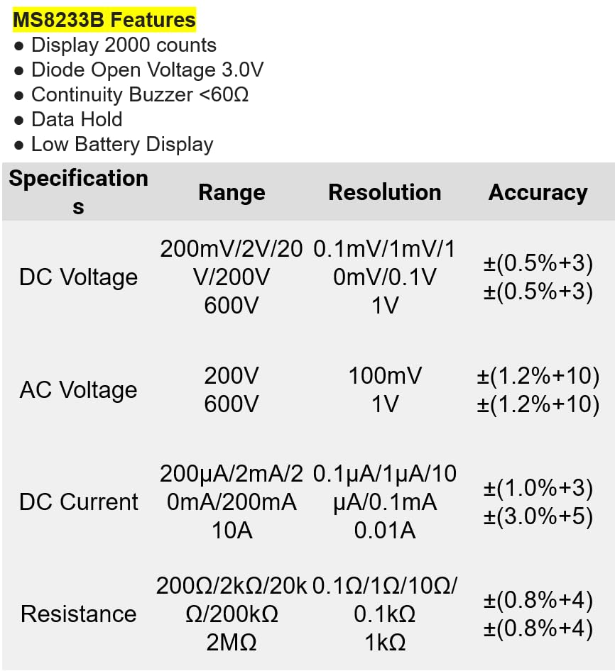
Figure 8.1: Detailed specifications for the Mastech MS8233B, including ranges, resolutions, and accuracies for various measurements.
| Specification | Value |
|---|---|
| Display | 2000 Counts |
| Diode Open Voltage | 3.0V |
| Continuity Buzzer | <60Ω |
| Data Hold | Yes |
| Low Battery Display | Yes |
| DC Voltage Range | 200mV, 2V, 20V, 200V, 600V |
| AC Voltage Range | 200V, 600V |
| DC Current Range | 200µA, 2mA, 20mA, 200mA, 10A |
| Resistance Range | 200Ω, 2kΩ, 20kΩ, 200kΩ, 2MΩ |
| Safety Rating | CAT III 600V |
| Power Source | 2 x LR44 Batteries (included) |
| Product Dimensions | 20 x 15 x 25 cm |
| Item Weight | 1 Kilogram |
| Manufacturer | MASTECH |
| Item Model Number | YQ-MS8233B |
| Country of Origin | Taiwan |

Figure 8.2: A comparison table showing features across various Mastech digital multimeter models, including the MS8233B.
9. Warranty and Support
For warranty information, technical support, or service inquiries, please refer to the documentation provided with your purchase or contact your retailer. Keep your purchase receipt as proof of purchase for any warranty claims.


