
1. Introduction
This manual provides detailed instructions for the installation, operation, and maintenance of your Breeze Bay Universal Ceiling Fan Remote Control Kit. This kit is designed to add remote control functionality to most standard AC ceiling fans, offering convenient control over fan speeds and lighting.

Image 1.1: The Breeze Bay Universal Ceiling Fan Remote Control Kit, showing the remote control and the receiver unit.
2. Safety Information
- Always disconnect power at the circuit breaker before installing or servicing the fan or remote control kit.
- Installation should be performed by a qualified electrician or a person with experience in electrical wiring.
- Ensure all wiring connections are secure and comply with local electrical codes.
- Do not use this kit with solid-state speed controls.
- This kit is compatible with most downrod style fans. It is not recommended for use with hugger style fans.
- The light dimmer function is primarily for incandescent lights. For LED/CFL bulbs, the remote will typically only control ON/OFF functionality, not dimming, unless the bulbs are specifically dimmable.
3. Packing List
Verify that all components are present before beginning installation:
- Remote Control (1)
- Receiver (1)
- Wall Mount Holder (1)
- User Guide (1)
- Wire Nuts (6)
- Screws (2)

Image 3.1: Visual representation of all items included in the Breeze Bay Universal Ceiling Fan Remote Control Kit: remote, receiver, wall holder, instructions, wire nuts, and screws.
4. Compatibility
This universal ceiling fan remote control kit is compatible with a wide range of ceiling fan lights, including many models from Hampton Bay, Hunter, allen+roth, Litex, Kichler, Westinghouse, and Honeywell. It is specifically designed to replace or work with the following remote control models:
- Hunter remote control models: 99392, 99770, 99813, 99815, 99384, 99772, 99122, 99123, 99600
- Other compatible models: FAN-53T, 2AAZPFAN53T, FAN-35T, L3HFAN35T1, FAN-11T, L3HFAN11T, KUJCE9103, KUJCE9603, CHQ8BT7030T, CHQ7030T, UC7030T, L3H2003FANHD, L3HFAN35T, L3HFAN35T2
Please check the part number on the back of your original remote control or the original model number to ensure compatibility.

Image 4.1: Visual guide indicating compatibility with various Hunter remote models (e.g., 99122/99123/99600 and 99770/99813/99392).
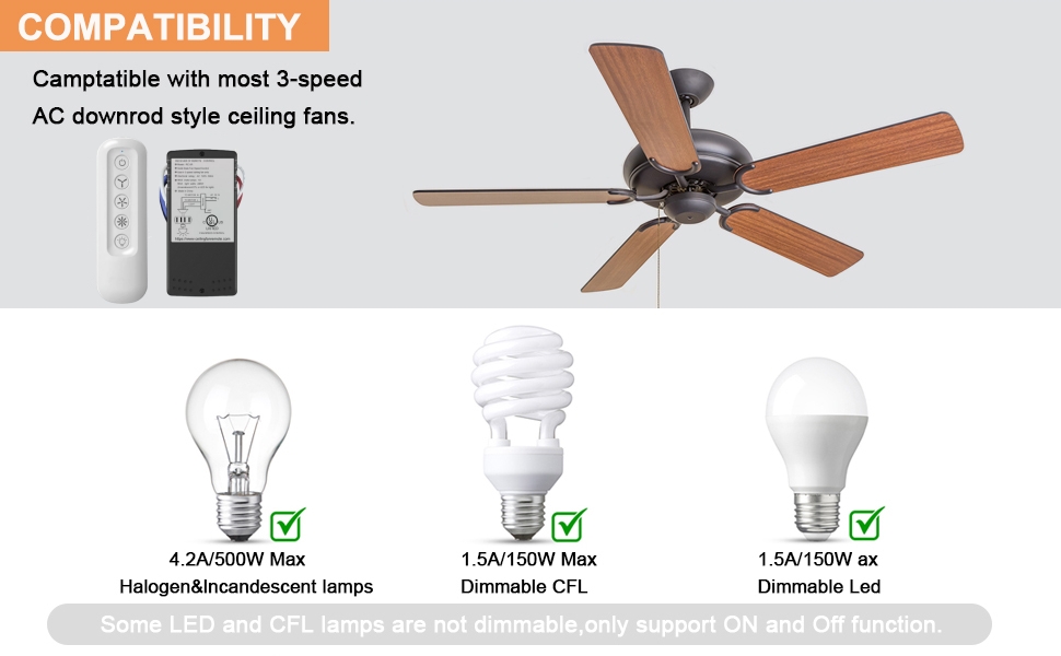
Image 4.2: Illustrates light bulb compatibility, showing that incandescent/halogen lamps are dimmable, while dimmable CFL and LED bulbs support ON/OFF and dimming if specified.
5. Specifications
| Feature | Detail |
|---|---|
| Package Dimensions | 5.79 x 4.88 x 1.73 inches |
| Item Weight | 5.9 ounces |
| Item Model Number | 99770/99392 Kit |
| Brand | Breeze Bay |
| Special Feature | Universal |
| Max Number of Supported Devices | 1 |
| Compatible Devices | AC Ceiling Fan |
| Connectivity Technology | Radio Frequency |
| Receiver Rated Power | 240W |

Image 5.1: Detailed size information for the remote control (11.4cm/4.48in length, 3.5cm/1.38in width), receiver (10.4cm/4.09in length, 5cm/1.97in width), and wall holder (4.8cm/1.89in height, 3.85cm/1.5in width).
6. Setup and Installation
6.1 Pre-Installation Steps
- Disconnect Power: Before starting any installation, ensure the power to the ceiling fan is turned off at the circuit breaker to prevent electrical shock.
- Prepare Fan: If your fan has a pull chain switch, set the fan speed to HIGH and the light to ON before installation. This ensures the receiver can take full control.
- Access Wiring: Remove the canopy cover of your ceiling fan to access the wiring connections.
6.2 Wiring Instructions
Follow the wiring diagram carefully. Use the provided wire nuts to secure all connections.

Image 6.1: Wiring diagram showing connections from AC 110-120V 60Hz power supply to the receiver (Red, White, Black wires) and from the receiver to the fan motor (Blue, Black, White wires) and light (White wire).
- Connect Power Input: Connect the AC 110-120V 60Hz power supply wires to the receiver's input wires:
- Black wire from power to Black wire on receiver.
- White wire from power to White wire on receiver.
- Connect Fan Motor Output: Connect the receiver's output wires to the ceiling fan motor wires:
- Blue wire from receiver to fan motor's Blue wire (for fan).
- Black wire from receiver to fan motor's Black wire (for fan).
- White wire from receiver to fan motor's White wire (for common neutral).
- Connect Light Output: Connect the receiver's output wire for the light to the ceiling fan's light wire:
- White wire from receiver to fan light's White wire.
- Secure Connections: Ensure all wire nuts are tightened securely.
6.3 Receiver Installation
- Carefully tuck the wired receiver into the fan's canopy. Ensure no wires are pinched.
- Reattach the canopy cover to the ceiling fan.
- Restore power at the circuit breaker.
7. Operating Instructions
The remote control features 5 buttons for comprehensive control of your ceiling fan and light.

Image 7.1: Overview of remote control features including 3-speed control (Low/Med/High/Off), light control (On/Off/Dimmer), blue indicator light, and a 'Learn Key' for pairing.
- Power Button (⏻): Turns the fan and light ON/OFF.
- Fan Speed Control (☁, ✽, ✽✽): These three buttons control the fan speed:
- One blade icon: Low speed
- Two blade icons: Medium speed
- Three blade icons: High speed
- Light Control (💡): Toggles the light ON/OFF. If held down, it activates the dimming function for compatible incandescent lights. The green button has a luminous feature to help locate it in the dark.
Note: This remote does not include a reverse function button for fan direction. The light dimmer button controls the brightness of incandescent lights. For LED/CFL bulbs, it will typically only control ON/OFF unless the bulbs are specifically designed for dimming.
8. Pairing Instructions
The receiver does not require setting a code. Pairing is a simple process:

Image 8.1: Diagram showing the location of the 'Learn Key' inside the remote control's battery compartment and the receiver unit, illustrating the pairing process.
- Install Battery: Open the remote control's battery compartment and insert a 3V battery (not included).
- Restore Power: Ensure power to the ceiling fan is restored at the circuit breaker.
- Initiate Pairing: Within 30 seconds of restoring power, press and hold the "LEARN" button (located inside the remote's battery compartment) for approximately 4 seconds.
- Confirmation: The fan light will flash, indicating successful pairing.
9. Maintenance
- Cleaning: Wipe the remote control and receiver with a soft, dry cloth. Do not use abrasive cleaners or solvents.
- Battery Replacement: Replace the remote control battery when its performance diminishes. Ensure correct polarity when inserting new batteries.
- Storage: Store the remote control in a dry place away from direct sunlight and extreme temperatures.
10. Troubleshooting
- Fan or Light Not Responding:
- Check if the power to the fan is ON at the circuit breaker.
- Ensure the remote control battery is installed correctly and has sufficient charge.
- Re-attempt the pairing process (Section 8).
- Verify all wiring connections are secure.
- Light Does Not Dim:
- Confirm that the light bulbs are incandescent or specifically labeled as dimmable LED/CFL. Non-dimmable LED/CFL bulbs will only turn ON/OFF.
- Intermittent Operation:
- Ensure the receiver is not obstructed within the fan canopy.
- Check for potential interference from other radio frequency devices.
11. Warranty and Support
For warranty information or technical support, please refer to the contact details provided with your purchase or visit the Breeze Bay official website. Keep your purchase receipt as proof of purchase.


