
Aoleaby B2A24S20P-HC
Aoleaby JK Smart BMS B2A24S20P-HC User Manual
For LiFePo4, Li-ion, and LTO Battery Systems
1. Introduction
The Aoleaby JK Smart Battery Management System (BMS) B2A24S20P-HC is an advanced electronic device designed to monitor and manage rechargeable batteries, ensuring their safe and efficient operation. This BMS features active balancing, Bluetooth (BT) communication, RS485, and CAN interfaces, making it suitable for a wide range of battery configurations from 8S to 24S, including LiFePo4, Li-ion, and LTO chemistries.
Its primary functions include protecting the battery from over-charge, over-discharge, over-current, and short circuits, while actively balancing cell voltages to maximize battery life and performance. This manual provides essential information for the proper installation, operation, and maintenance of your JK Smart BMS.

Image 1.1: The Aoleaby JK Smart BMS B2A24S20P-HC unit. This image displays the main BMS unit with its input and output terminals, along with a QR code for app access and cell voltage monitoring points.
2. Package Contents
Please verify that all items listed below are included in your package:
- JK Smart BMS Unit
- Instruction Manual
- NTC Temperature Sensor (40cm)
- Heating Cable (16cm)
- CAN Cable (25cm)
- Switch (50cm)
- Balance Wires (70cm)

Image 2.1: Contents of the Aoleaby JK Smart BMS B2A24S20P-HC package. This image shows the BMS unit, the instruction manual, the packaging box, an NTC temperature sensor, a heating cable, a CAN cable, a switch, and the balance wires.
3. Key Features
- JK Own Development APP: Access BMS settings and real-time battery status via Bluetooth communication on your smartphone.
- JK Active Balance: Actively balances voltage differences between battery cells, improving battery usage efficiency up to 99% and extending battery life.
- Comprehensive Protection: Protects against over-charge, over-discharge, over-current, short circuit, and includes low-temperature charging cutoff.
- Wide Compatibility: Supports 8S to 24S LiFePo4, Li-ion, and LTO battery systems.
- High Current Capability: Handles 100A-350A maximum current with 0.6-2A active balance current.
- Communication Interfaces: Equipped with Bluetooth, RS485, and CAN communication for versatile integration.

Image 3.1: Key features of the Aoleaby JK Smart BMS B2A24S20P-HC. This graphic highlights the model number B2A24S20P, BT/RS485 function, 2A balance current, 8S-24S battery string support, 200A charge/discharge current, dimensions (162*102*20mm), and compatibility with Li-ion/LiFePo4/LTO battery types.

Image 3.2: General features of JK Smart BMS. This image illustrates the broad range of battery string support (3S~24S), current handling (40A~200A), and active balance current (0.4A~2A) across the JK BMS product line.
4. Technical Specifications
General Specifications:
- Brand: Aoleaby
- Model Name: Aoleaby (Note: Specific model is B2A24S20P-HC)
- Item Weight: 2.2 pounds (approximately 1000 Grams)
- Package Dimensions: 1.18 x 0.79 x 0.39 inches
- Number of pieces: 1
Model B2A24S20P-HC Specifics:
| Feature | Specification |
|---|---|
| LiFePo4 String Supported | 8-24S |
| Li-ion String Supported | 8-24S |
| LTO String Supported | 12-24S |
| Active Balance Current | 2A |
| Inner Resistance of Main Chip | 0.3mΩ |
| Charge Current | 200A |
| Discharge Current | 200A |
| Max Discharge Current (2X) | 350A |
| Overcurrent (A) Adjustable | 10-1000A |
| Other Interface | RS485, CANBUS |
| Dimensions (L*W*H) | 189*94*24 mm |
| Wiring Diagram Type | Split Port |
| Voltage Acquisition Range | 1-5V |
| Voltage Acquisition Accuracy | ±5mV |
| Overcharge Protection Voltage | 1.2-4.35V Adjustable |
| Overcharge Release Voltage | 1.2-4.35V Adjustable |
| Overcurrent Release Delay Time | 2-120S Adjustable |
| Protection Voltage | 1.2-4.35V Adjustable |
| Release Voltage | 1.2-4.35V Adjustable |
| Temperature Sensors | 3 pcs |
| Short Circuit Protection | Yes |
| Coulometer Function | Yes |
| Heated Function | Yes |
| IOS/Android App Support | Yes |
Image 4.1: Detailed Product Specifications Table. This table provides comprehensive technical data for various JK BMS models, including the B2A24S20P, covering string support, balance current, charge/discharge current, dimensions, and protection features.
5. Setup and Installation
Proper installation is crucial for the safe and effective operation of your BMS. Always ensure the battery pack is disconnected from any power sources before beginning installation. Refer to the wiring diagram carefully.
Wiring Instructions:
- Connect Balance Wires: Connect the balance wires from the BMS to each cell of your battery pack, starting from the first string (1st string) to the last string. Ensure correct polarity for each connection. The diagram shows connections for B- (total negative electrode) and B+ (total positive pole), with individual cell sampling cables.
- Connect P- Terminal: Connect the P- terminal of the BMS to the negative terminal of your load (motor, etc.) and charger.
- Connect B- Terminal: Connect the B- terminal of the BMS to the total negative electrode of your battery pack.
- Connect P+ Terminal: Connect the P+ terminal of the BMS to the positive terminal of your load and charger. This connection typically bypasses the BMS for the positive side, with the BMS managing the negative path for protection.
- Optional Connections: Connect the NTC temperature sensor, heating cable, CAN cable, and switch as required for your specific application.
Safety Note: Double-check all connections for correct polarity and secure fitment before applying power. Incorrect wiring can damage the BMS, battery, or connected devices.
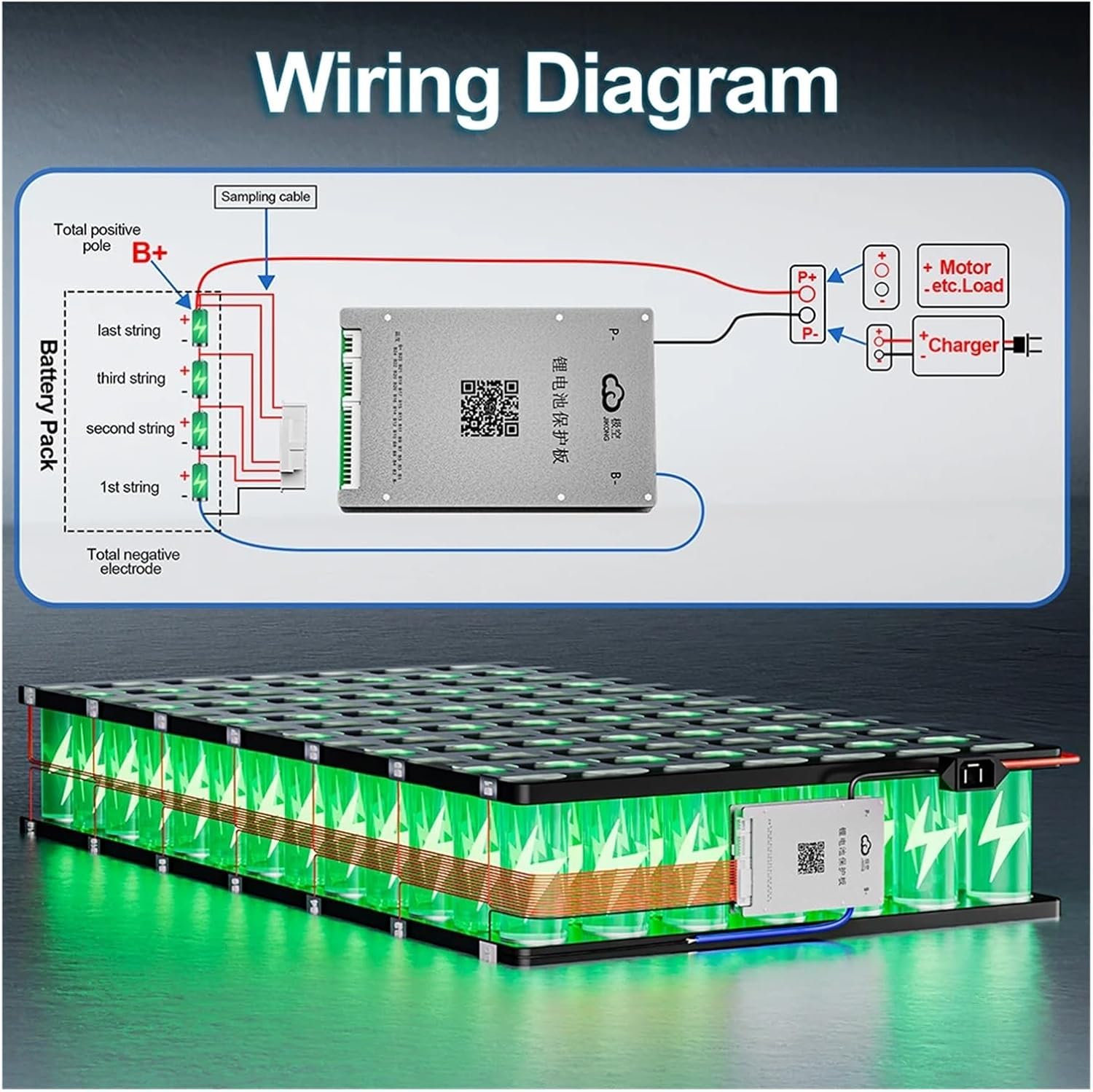
Image 5.1: Wiring Diagram for JK Smart BMS. This diagram illustrates how to connect the BMS to a battery pack, including the balance wires, main positive (B+) and negative (B-) terminals, and connections to the motor/load and charger.
6. Operating the Smart BT APP
The JK Smart BMS features a dedicated Bluetooth application for real-time monitoring and configuration. The app supports both Android and iOS systems.
App Functions:
- Real-time Data Monitoring: View battery power, voltage, current, cell voltages, temperature, cycle count, and remaining capacity.
- Parameter Modification: Adjust various BMS parameters such as over-charge/discharge protection voltages, over-current limits, and balance settings.
- BMS Balance Switch Control: Manually control the active balance function.
To download the app, scan the QR code on the BMS unit or visit the official download link: http://qr17.cn/BApbC0

Image 6.1: Smart BT APP interface for JK Smart BMS. This image shows a smartphone screen displaying the app, which monitors battery data in real-time, supports parameter modification, and allows control of the BMS balance switch. The app is compatible with Android and iOS systems.
7. Maintenance
To ensure the longevity and optimal performance of your JK Smart BMS and battery pack, follow these maintenance guidelines:
- Regular Monitoring: Periodically check battery parameters via the Smart BT APP to identify any anomalies early.
- Cleanliness: Keep the BMS unit clean and free from dust, dirt, and moisture. Use a dry, soft cloth for cleaning.
- Connection Integrity: Periodically inspect all wiring connections for tightness and corrosion. Loose connections can lead to poor performance or damage.
- Temperature Management: Ensure the BMS and battery pack operate within their specified temperature ranges. Avoid extreme heat or cold.
- Firmware Updates: Check for any available firmware updates for the BMS through the app or manufacturer's website to ensure you have the latest features and bug fixes.
8. Troubleshooting
If you encounter issues with your JK Smart BMS, consider the following common troubleshooting steps:
- BMS Not Powering On: Verify all main power connections (B- and P-) are correctly wired and secure. Check the battery pack voltage.
- App Connection Issues: Ensure Bluetooth is enabled on your smartphone and the BMS is within range. Restart the app and the BMS (if possible). Confirm the correct BMS model is selected in the app.
- Cell Voltage Imbalance: Allow the BMS sufficient time to perform active balancing. If imbalance persists, check individual balance wire connections for continuity and correct placement.
- Over-Protection Triggered: If the BMS frequently triggers over-charge, over-discharge, or over-current protection, review your battery usage patterns and BMS settings. Adjust parameters within safe limits if necessary, or reduce load/charge current. Check for short circuits in the system.
- Temperature Alarms: Ensure the NTC temperature sensors are correctly installed and making good contact with the battery cells. Verify ambient temperature is within operating limits.
For persistent issues, consult the manufacturer's support resources or contact customer service.
9. Warranty and Support
For warranty information and technical support regarding your Aoleaby JK Smart BMS B2A24S20P-HC, please refer to the documentation provided at the time of purchase or contact the manufacturer directly. Keep your purchase receipt as proof of purchase for warranty claims.
Manufacturer: Aoleaby
Ask a question about this manual
Ask about setup, troubleshooting, compatibility, parts, safety, or missing instructions. Manuals+ will review the question and use this page’s manual context to help answer it.