
Aoleaby B1A8S10P-HC
JK Smart BMS B1A8S10P-HC User Manual
Model: B1A8S10P-HC | Brand: Aoleaby
1. Introduction
This manual provides detailed instructions for the installation, operation, and maintenance of your JK Smart BMS B1A8S10P-HC. This Battery Management System is designed to protect and optimize the performance of 4S to 8S Li-ion, LiFePo4, and LTO battery packs, ensuring their longevity and safe operation. It features active balancing, comprehensive protection functions, and Bluetooth connectivity for convenient monitoring.

Figure 1: JK Smart BMS B1A8S10P-HC unit. This image displays the primary components and the QR code for accessing the APP and user instructions.
2. Key Features
- JK Own Development APP: Utilizes a dedicated mobile application for comprehensive BMS settings and real-time battery status display via Bluetooth communication.
- JK Active Balance: Features active balancing to equalize voltage differences between battery cells, significantly improving battery usage efficiency (up to 99%) and extending battery life.
- Full Functionality Protection: Provides robust protection against over-charge, over-discharge, over-current, and short circuits. Includes a low-temperature charging cutoff for enhanced safety.
- Enhanced Safety Design: Uniquely designed to ensure the correct protection board application, which is crucial for the longevity and safety of your battery system.
- Wide Compatibility: Supports 12V/4S, 24V/8S, 48V/16S, and 72V/24S LiFePo4 battery systems with a maximum continuous discharge current of 100A-350A and an active balance current of 0.6A-2A, making it suitable for various DIY applications.

Figure 2: Feature overview of the JK Smart BMS B1A8S10P-HC, detailing its communication protocols, balance current, supported battery configurations, and physical dimensions.
3. Product Specifications
The following table outlines the detailed technical specifications for the JK Smart BMS B1A8S10P-HC model. For a comprehensive list of all JK BMS models and their specifications, please refer to the detailed product specification table image below.
| Specification | Value |
|---|---|
| Model Name | B1A8S10P-HC |
| Supported Battery Strings | 4S-8S |
| Active Balance Current | 1A |
| Continuous Discharge Current | 100A |
| Communication Interfaces | Bluetooth (BT), CAN, RS485 |
| Heating Function | Yes |
| Dimensions (L x W x H) | 153 x 136 x 18 mm (approx.) |
| Item Weight | 2.2 pounds (approx. 1000 grams) |

Figure 3: Comprehensive product specifications table for the JK Smart BMS series, including the B1A8S10P-HC model. This table provides detailed electrical and physical parameters.
4. Package Contents
Upon opening the package, please verify that all the following components are included and in good condition:
- JK Smart BMS Unit (B1A8S10P-HC)
- Operating Manual
- NTC Temperature Sensor (40cm)
- Switch (50cm)
- Balance Wires (70cm)
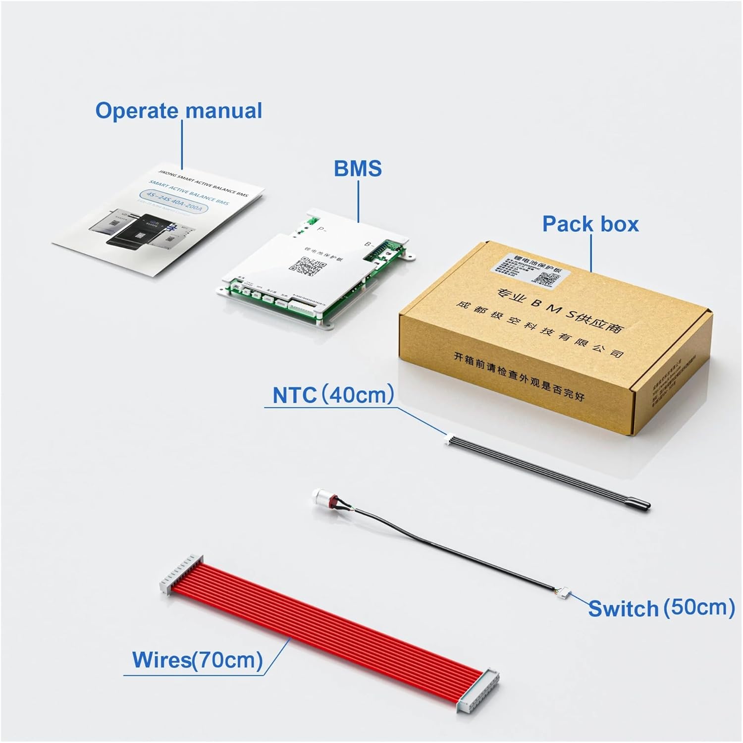
Figure 4: Contents of the JK Smart BMS B1A8S10P-HC package. Ensure all listed items are present before proceeding with installation.
5. Setup and Wiring
Proper wiring is critical for the safe and effective operation of your BMS. Please follow the wiring diagram carefully. Incorrect wiring can lead to damage to the BMS, battery pack, or connected equipment.
5.1 Wiring Diagram Overview
The diagram illustrates the connections between the BMS, the battery pack, and the charger/load. The sampling cable connects to individual cell strings, while the main power cables connect to the total positive (B+) and negative (P-) terminals of the BMS.
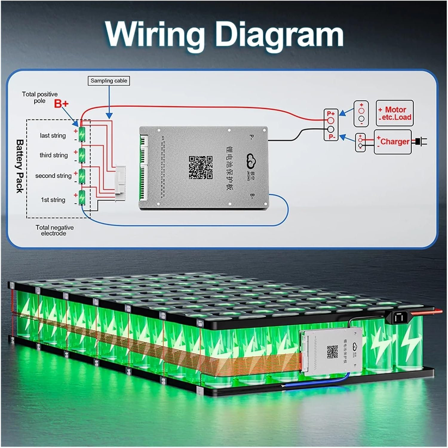
Figure 5: Wiring diagram for the JK Smart BMS. This diagram shows how to connect the BMS to your battery pack, charger, and load. Pay close attention to the balance wire connections.
5.2 Connection Steps
- Prepare Battery Pack: Ensure your battery pack is assembled correctly with all cells balanced to a similar voltage before connecting the BMS.
- Connect Balance Wires: Connect the balance wires from the battery pack to the corresponding ports on the BMS. Ensure the order is correct, starting from the lowest cell voltage.
- Connect Main Power Cables: Connect the main positive (B+) and negative (P-) terminals of the BMS to the battery pack's main terminals.
- Connect Charger/Load: Connect your charger and load to the designated terminals on the BMS.
- Install Temperature Sensor: Securely attach the NTC temperature sensor to a central cell within the battery pack to monitor its temperature.
- Power On: Once all connections are verified, you can power on the system.
For detailed step-by-step wiring instructions and video tutorials, please scan the QR code found on the BMS unit or refer to the official online resources: http://qr17.cn/BApbC0
6. Operation
6.1 Using the JK BMS APP
The JK Smart BMS features a dedicated mobile application that allows you to monitor your battery pack's status in real-time and configure various BMS parameters. The APP connects to the BMS via Bluetooth.
- Download APP: Scan the QR code on the BMS unit or visit http://qr17.cn/BApbC0 to download the official JK BMS APP for your smartphone.
- Connect via Bluetooth: Enable Bluetooth on your phone and open the JK BMS APP. The APP will automatically search for nearby BMS devices. Select your BMS from the list to connect.
- Monitor Battery Status: Once connected, you can view real-time data such as cell voltages, total voltage, current, temperature, state of charge (SOC), and protection status.
- Configure Settings: The APP allows you to adjust various parameters, including over-charge/discharge voltage limits, over-current thresholds, and balance settings. Refer to the in-app help or online manual for detailed parameter explanations.
6.2 Active Balancing Function
The active balancing feature automatically works to equalize the voltage across all cells in your battery pack. This process helps prevent cell imbalance, which can reduce battery capacity and lifespan. The 1A active balance current ensures efficient and rapid balancing.
7. Maintenance
To ensure the long-term performance and reliability of your JK Smart BMS and battery pack, consider the following maintenance guidelines:
- Regular Monitoring: Periodically check the battery status via the JK BMS APP to ensure all cells are balanced and operating within safe parameters.
- Clean Connections: Ensure all wiring connections are clean, tight, and free from corrosion. Loose connections can lead to resistance and heat buildup.
- Environmental Conditions: Operate the BMS and battery pack within their specified temperature ranges. Avoid extreme heat, cold, or high humidity.
- Firmware Updates: Check for any available firmware updates for your BMS via the APP or official website. Updates can improve performance and add new features.
- Physical Inspection: Occasionally inspect the BMS unit for any signs of physical damage, overheating, or unusual odors.
8. Troubleshooting
If you encounter issues with your JK Smart BMS, refer to the following common troubleshooting steps:
- BMS Not Powering On:
- Check all main power connections (B+ and P-) to ensure they are secure and correctly wired.
- Verify the battery pack voltage is within the BMS's operating range.
- Bluetooth Connection Issues:
- Ensure Bluetooth is enabled on your smartphone.
- Make sure the BMS is powered on and within Bluetooth range.
- Try restarting the APP or your phone.
- Cell Imbalance:
- Confirm all balance wires are correctly connected to the BMS and individual cells.
- Allow the BMS sufficient time to perform active balancing, especially after initial setup or deep discharge.
- Over-Protection Triggered (Over-charge, Over-discharge, Over-current):
- Check the battery voltage and current draw against the BMS settings in the APP.
- Ensure your charger and load are compatible with the battery pack and BMS limits.
- If an over-current protection triggers frequently, reduce the load or consider a BMS with a higher current rating.
- Temperature Protection:
- Verify the NTC temperature sensor is properly installed and making good contact with a cell.
- Ensure the battery pack is operating within its safe temperature range.
For more complex issues or if the problem persists, please contact customer support or refer to the detailed troubleshooting guides available via the QR code link: http://qr17.cn/BApbC0
9. Warranty and Support
Aoleaby is committed to providing high-quality products and customer satisfaction. For warranty information, technical support, or service inquiries, please refer to the contact details provided with your purchase documentation or visit the official Aoleaby website. Please have your product model number (B1A8S10P-HC) and purchase date ready when contacting support.
Ask a question about this manual
Ask about setup, troubleshooting, compatibility, parts, safety, or missing instructions. Manuals+ will review the question and use this page’s manual context to help answer it.