
Introduction
This manual provides comprehensive instructions for the Binardat 10 Port Gigabit L2+ Managed Industrial PoE Switch. This device is designed to offer a reliable and convenient industrial network solution, featuring robust construction and advanced management capabilities. Please read this manual thoroughly before installation and operation to ensure proper use and optimal performance.
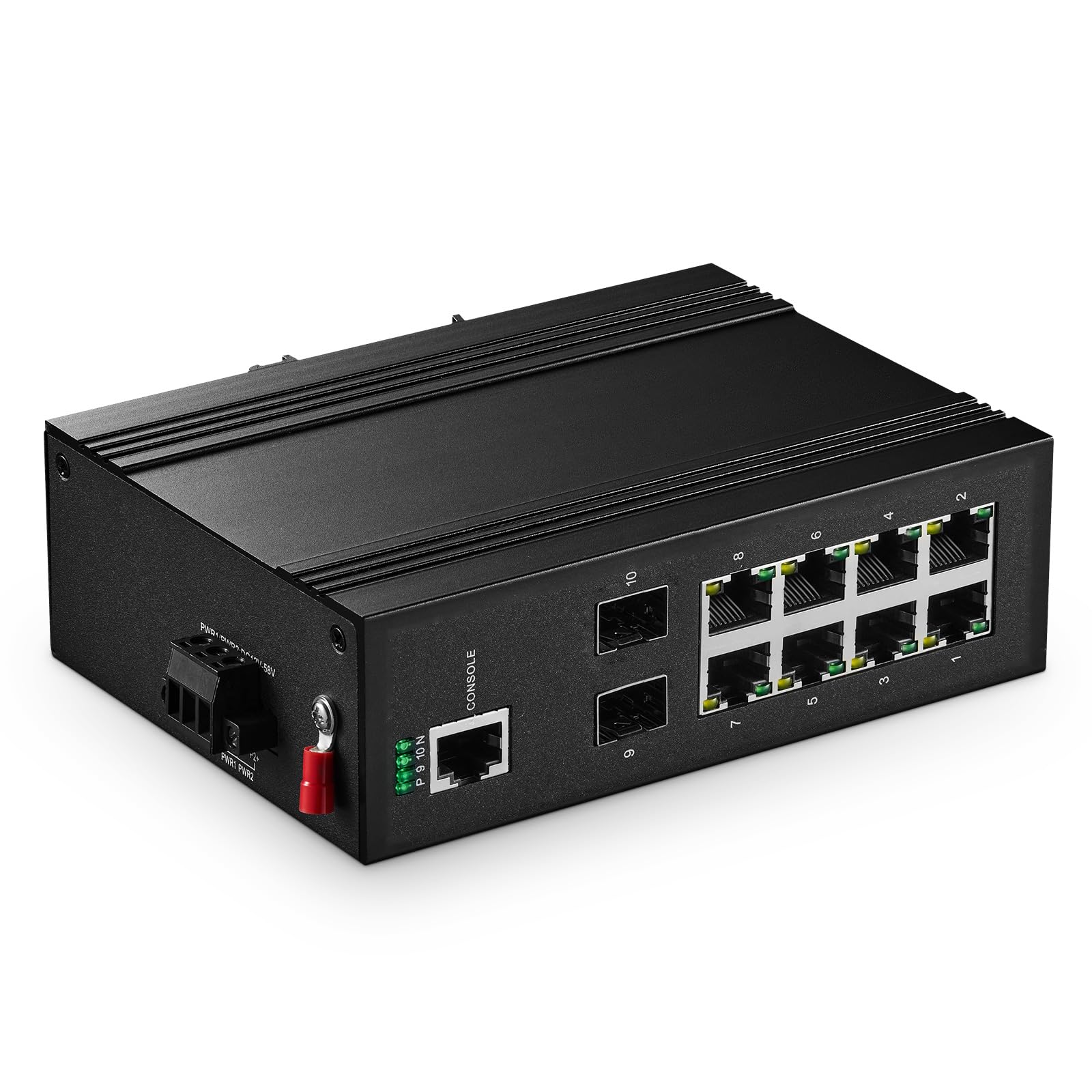
Figure 1: Binardat 10 Port Gigabit L2+ Managed Industrial PoE Switch overview, highlighting features like IEEE 802.3af/at support, redundant power supply, IP40 protection, Gigabit ports, L2 features, Web+CLI interface, DIN rail mountable, and -30°C to +75°C operating temperature.
Setup
1. Package Contents
Verify that the following items are included in your package:
- Industrial PoE Switch
- DIN Mount Kit
- User Manual
2. Physical Installation
The switch supports both DIN rail and wall mounting. Use the provided DIN Mount Kit for installation.

Figure 2: The switch's compact size (5.63 x 4.09 x 1.81 inches), 4KV lightning protection, fanless and sturdy housing, and DIN rail mountable design, suitable for industrial environments.
3. Power Connection
The switch features a dual redundant power input design for enhanced reliability. Connect a DC power supply (not included) to the terminal block. The input voltage for PoE functionality must be 48-55V DC. The switch supports a wide voltage input range of DC12-58V.
Important: For PoE to function, the input voltage must be 48-55V DC. Passive 24V PoE is not supported.
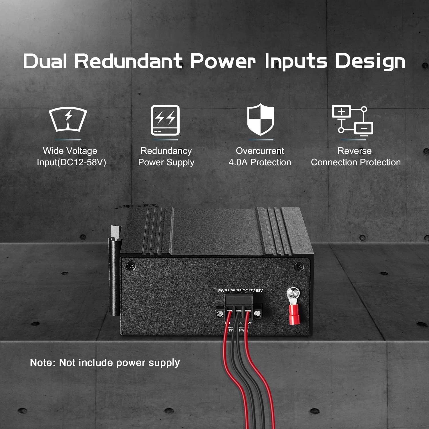
Figure 3: Dual redundant power inputs (PWR1, PWR2) supporting DC12-58V, with features like wide voltage input, redundancy power supply, 4.0A overcurrent protection, and reverse connection protection. Note: Power supply is not included.
4. Network Connections
- Ethernet Ports (1-8): Connect your PoE-compatible devices (e.g., IP cameras, IP phones, wireless access points) or standard network devices using RJ45 Ethernet cables. These ports support 10/100/1000Mbps adaptive speeds.
- SFP Slots (9-10): Insert Gigabit SFP modules (not included) for fiber optic connections. These slots support single/multi-fiber connections.
- Console Port: Use the console port for Command Line Interface (CLI) management.
Operating Instructions
1. Power over Ethernet (PoE) Functionality
Ports 1-8 support IEEE 802.3af/at PoE standards, providing up to 30W of power per port. This allows for direct power and data transmission to compatible devices over a single Ethernet cable.
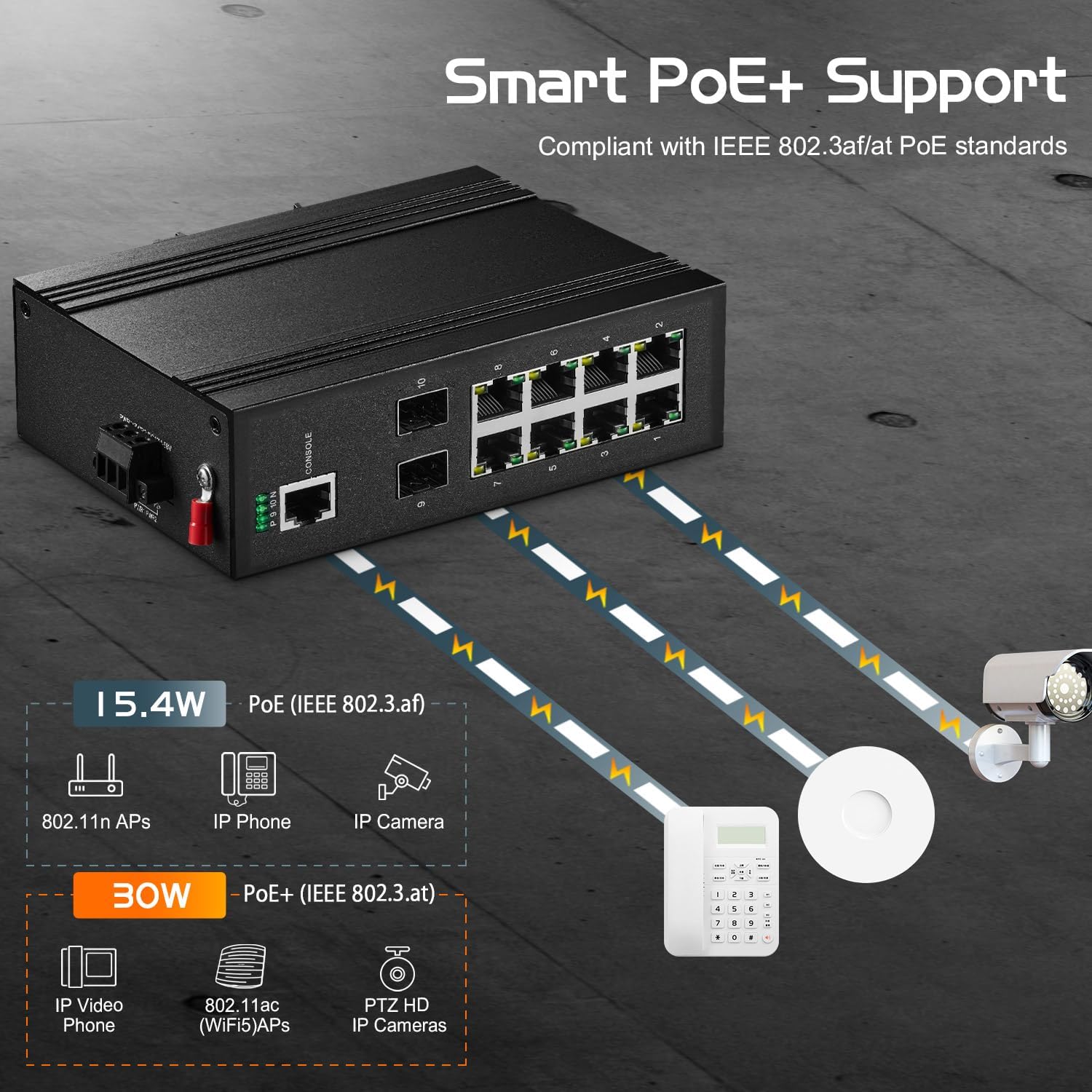
Figure 4: Smart PoE+ support compliant with IEEE 802.3af/at PoE standards. Illustrates 15.4W PoE (IEEE 802.3af) for devices like 802.11n APs, IP Phones, and IP Cameras, and 30W PoE+ (IEEE 802.3at) for IP Video Phones, 802.11ac (WiFi5) APs, and PTZ HD IP Cameras.
2. L2+ Management Features
The switch offers advanced Layer 2+ management capabilities via Web and Command Line Interface (CLI). Key features include:
- VLAN: Supports 4K VLANs for network segmentation.
- MAC Table: 8K MAC address table for efficient forwarding.
- ACL/QoS: Access Control Lists and Quality of Service for traffic management.
- Security: Port security and flow control.
- Spanning Tree Protocols: STP/RSTP/MSTP for loop prevention.
- Storm Suppression: Prevents network broadcast storms.
- Network Topology: Supports ring/star network topologies.
- L2+ Functions: Includes IPv4/IPv6, ARP, static routing, and DHCP.

Figure 5: Layer2+ Managed Industrial Switch with powerful software features such as SNMP, LLDP, RSTP, Route, ACL, IGMP, LACP, QoS, and VLAN.
3. Management Access
The switch can be managed via a web interface or Command Line Interface (CLI).
- Web Interface: Access the web interface by connecting a computer to one of the switch's Ethernet ports and navigating to the default IP address: 192.168.2.1. Default Username: admin, Default Password: admin.
- CLI: Connect to the console port using a serial cable and a terminal emulator. Supports TELNET, SSH, SNMP, and RMON management.

Figure 6: Flexible management and operation supporting WEB, CLI, TELNET, SSH, SNMP, RMON management. Shows the default IP, username, and password for web access, and an example of the command line interface.
4. LED Indicators
The power and port indicators provide clear visual feedback on the device's operational status. Refer to the full user manual for detailed LED status interpretations.
Maintenance
1. Industrial Grade Design
The switch features a robust IP40-rated aluminum alloy housing and industrial-grade electronic components, ensuring durability and reliable operation in harsh environments.

Figure 7: The switch is suitable for industrial environments, featuring an IP40 metal housing and a wide operating temperature range from -30°C (low temperature resistant) to +75°C (high temperature resistant).
2. Environmental Resilience
Designed for industrial use, the switch operates reliably in temperatures ranging from -40°C to 75°C (-40°F to 185°F). It includes lightning protection, anti-static protection, and overload protection.
3. Redundant Power for Continuous Operation
The dual-way industrial-grade power interfaces automatically switch to the secondary power source in case of a primary power failure, ensuring high reliability and continuous business operation without downtime.
4. Fanless Design
The fanless design, coupled with a heat sink for heat dissipation, ensures quiet operation and energy efficiency.
Troubleshooting
1. No Power
- Ensure the power supply is correctly connected to the terminal block.
- Verify that the power supply is providing the correct voltage (DC12-58V).
- Check the power LED indicators on the switch.
2. No PoE Output
- Confirm that the input DC voltage is within the 48-55V range required for PoE.
- Ensure the connected device is PoE-compatible (IEEE 802.3af/at standard).
- Check the PoE status LEDs for the respective ports.
- Verify that the total power budget is not exceeded.
3. Network Connectivity Issues
- Check Ethernet cable connections for all devices.
- Verify port link/activity LEDs.
- Ensure IP address settings are correct for managed access (default 192.168.2.1).
- If using SFP ports, ensure SFP modules are correctly inserted and compatible.
4. Accessing Management Interface
- If unable to access the web interface, ensure your computer's IP address is in the same subnet as the switch (e.g., 192.168.2.x).
- Confirm default login credentials (admin/admin).
- For CLI access, ensure the console cable is properly connected and terminal emulator settings are correct.
Specifications
| Model Number | ING10-082GSMP |
| Brand | Binardat |
| Number of Ports | 10 (8 Gigabit PoE, 2 Gigabit SFP) |
| Ethernet Ports | 8 x 10/100/1000Mbps RJ45 (PoE) |
| SFP Ports | 2 x 1000Mbps SFP (supports Single/Multi Fiber) |
| Switching Capacity | 20 Gbps |
| PoE Standard | IEEE 802.3af/at |
| Max PoE Power per Port | 30W |
| Input Voltage | DC 12-58V (DC 48-55V for PoE) |
| Operating Temperature | -40°C to 75°C (-40°F to 185°F) |
| Housing Material | Aluminum Alloy |
| IP Rating | IP40 |
| Management | Web, CLI, TELNET, SSH, SNMP, RMON |
| Dimensions | 5.63 x 4.09 x 1.81 inches (14.3 x 10.4 x 4.6 cm) |
| Compatible Devices | Camera, Printer, Smartphone, Tablet, Laptop, Server, Desktop |
Warranty and Support
Information regarding product warranty, availability of spare parts, and guaranteed software updates is not provided in the product details. For specific warranty terms, technical support, or service inquiries, please contact Binardat directly or refer to their official website.