
1. Introduction
This manual provides essential instructions for the safe and efficient use of the Cisco PWR-C5-125WAC Power Supply. This unit is designed to provide reliable 125W power delivery for Cisco Catalyst 9200L Series Switches, ensuring consistent operation of network equipment. Please read this manual thoroughly before installation and operation.
2. Safety Information
Observe the following safety precautions to prevent injury and damage to the equipment:
- Ensure the power supply is disconnected from the power source before installation or removal.
- Only qualified personnel should perform installation and servicing.
- Do not operate the power supply in wet or damp conditions.
- Verify that the input voltage matches the power supply's specifications.
- Use only approved power cords and connectors.
3. Setup and Installation
Follow these steps to properly install the Cisco PWR-C5-125WAC Power Supply into a compatible Catalyst 9200L Series Switch chassis.
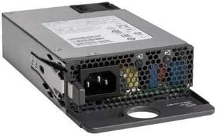
This image displays the Cisco PWR-C5-125WAC Power Supply unit. The front panel features the AC power input connector (IEC 60320 C14 type) and ventilation grilles. The overall form factor is compact, designed for integration into network switch chassis.
- Prepare the Switch Chassis: Ensure the Catalyst 9200L Series Switch is powered off and disconnected from all power sources. Locate the power supply bay on the switch chassis.
- Remove Filler Panel (if present): If a blank filler panel is installed in the power supply bay, carefully remove it by loosening any retaining screws or clips.
- Insert the Power Supply: Align the PWR-C5-125WAC power supply with the open bay. Gently slide the power supply into the bay until it is fully seated. Ensure the connector aligns correctly with the backplane.
- Secure the Power Supply: Once seated, secure the power supply using any provided thumbscrews or locking mechanisms on the unit or chassis.
- Connect Power Cable: Connect a compatible IEC 60320 C14 power cable to the AC input port on the power supply. Connect the other end of the power cable to a grounded electrical outlet.
- Power On: After verifying all connections are secure, power on the Catalyst 9200L Series Switch. The power supply status indicator should illuminate, indicating proper operation.
4. Operating Instructions
The Cisco PWR-C5-125WAC Power Supply operates automatically once installed and connected to a power source. It provides continuous power to the connected Catalyst 9200L Series Switch.
Status Indicators
Refer to the switch's documentation for specific LED indicators related to power supply status. Typically, a solid green LED indicates normal operation, while an amber or off LED may indicate a fault or no power.
5. Maintenance
The Cisco PWR-C5-125WAC Power Supply is designed for minimal maintenance. However, periodic checks can help ensure optimal performance:
- Ventilation: Ensure that the ventilation grilles on the power supply and switch chassis are clear of obstructions to allow for proper airflow and cooling.
- Cable Connections: Periodically check that all power cables are securely connected and free from damage.
- Environmental Conditions: Operate the power supply within the recommended temperature and humidity ranges specified for the Catalyst 9200L Series Switch.
- Cleaning: If necessary, gently clean the exterior of the power supply with a dry, lint-free cloth. Do not use liquid cleaners.
6. Troubleshooting
If you encounter issues with the power supply, consider the following troubleshooting steps:
- No Power:
- Verify the power cable is securely connected to both the power supply and the electrical outlet.
- Check if the electrical outlet is functional by plugging in another device.
- Ensure the switch's power button (if applicable) is in the 'On' position.
- Intermittent Power:
- Inspect the power cable for any signs of damage. Replace if necessary.
- Ensure the power supply is fully seated in its bay within the switch chassis.
- Overheating:
- Check for obstructions around the ventilation grilles of the power supply and switch.
- Ensure the operating environment temperature is within specified limits.
If these steps do not resolve the issue, consult the Cisco Catalyst 9200L Series Switch documentation or contact Cisco support.
7. Specifications
Key technical specifications for the Cisco PWR-C5-125WAC Power Supply:
| Feature | Specification |
|---|---|
| Brand | Cisco |
| Model Number | PWR-C5-125WAC |
| Output Wattage | 125 Watts |
| Form Factor | ATX |
| Connector Type | IEC 60320 C14 |
| Cooling Method | Air |
| Maximum Input Voltage | 240 Volts (AC) |
| UPC | 796575187955 |
8. Warranty and Support
For information regarding warranty coverage, technical support, or service for your Cisco PWR-C5-125WAC Power Supply, please refer to the documentation provided with your Cisco Catalyst 9200L Series Switch or contact your authorized Cisco reseller or Cisco Systems directly. Support options and warranty terms may vary based on region and purchase agreement.


