
Genmitsu 3020-PRO MAX V2
Genmitsu 3020-PRO MAX V2 CNC Router Machine and Y-Axis Extension Kit User Manual
Model: 3020-PRO MAX V2
Brand: Genmitsu
1. Introduction
This manual provides detailed instructions for the assembly, operation, and maintenance of your Genmitsu 3020-PRO MAX V2 CNC Router Machine and the accompanying 3020 Y-Axis Extension Kit. Please read this manual thoroughly before operating the machine to ensure safe and efficient use. The Genmitsu 3020-PRO MAX V2 is designed for precision carving, engraving, and milling various materials, offering enhanced stability and expanded functionality.

Image 1.1: The Genmitsu 3020-PRO MAX V2 CNC Router Machine.
2. Safety Guidelines
Operating a CNC machine involves potential hazards. Adhere to the following safety guidelines to prevent injury and damage:
- Read the Manual: Understand all instructions before operation.
- Personal Protective Equipment (PPE): Always wear safety glasses to protect against flying debris. Consider hearing protection and dust masks.
- Work Area: Ensure your workspace is clean, well-lit, and free of obstructions. Keep children and unauthorized personnel away.
- Emergency Stop: Familiarize yourself with the location and function of the emergency stop button.
- Power Disconnection: Always disconnect power before performing maintenance, adjustments, or when leaving the machine unattended.
- Material Securing: Ensure workpieces are securely clamped to the spoilboard to prevent movement during operation.
- Tooling: Use appropriate and sharp cutting tools for the material being processed. Inspect tools for damage before use.
- Dust and Debris: Manage dust and chips effectively. Consider a dust shoe and vacuum system.
- Electrical Safety: Do not operate the machine with wet hands or in damp conditions. Ensure all electrical connections are secure.
3. Package Contents
Verify that all components listed below are present in your package:
- Genmitsu 3020-PRO MAX V2 CNC Router Machine (main unit)
- 3020 Y-Axis Extension Kit (includes longer aluminum profiles and guide rails)
- Power Supply
- Spindle Motor
- Offline Controller (optional, may be included)
- Limit Switches
- Photoelectric Z-probe
- Rubber Feet
- Clamps
- Tools for Assembly
- USB Cable
- User Manual (this document)
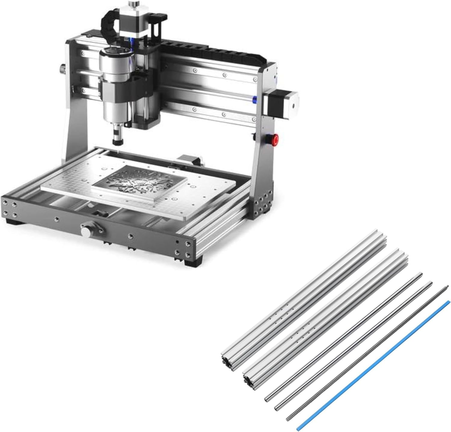
Image 3.1: Main components of the Genmitsu 3020-PRO MAX V2 CNC Router Machine and the Y-Axis Extension Kit.
4. Assembly Instructions
Follow these steps carefully for proper assembly of your CNC machine.
4.1 Main Machine Assembly
- Install Rubber Feet: Attach the rubber feet to the base of the machine frame.
- Connect XZ Assembly with Platform: Secure the XZ axis assembly to the main platform.
- Install Spindle Mount & Spindle: Mount the spindle bracket and then insert the spindle motor.
- Wiring: Connect all necessary wires according to the provided wiring diagram (refer to the separate wiring guide if included).

Image 4.1: Visual guide for the main machine assembly steps.
4.2 Y-Axis Extension Kit Assembly
The Y-Axis Extension Kit increases your machine's working area. This process involves replacing the existing Y-axis components with longer ones.
- Disassemble Existing Y-Axis: Carefully remove the original Y-axis aluminum profiles and guide rails.
- Install Longer Profiles: Attach the new, longer aluminum profiles for the Y-axis to the machine base.
- Install Longer Guide Rails: Insert the longer guide rails into the new Y-axis profiles.
- Reassemble Moving Platform: Reattach the moving platform to the extended Y-axis, ensuring smooth movement.
- Secure Components: Tighten all screws and ensure all connections are firm.

Image 4.2: The Y-Axis Extension Kit components, including longer profiles and guide rails.

Image 4.3: Illustration of the increased working area after installing the Y-axis extension, showing dimensions.
5. Component Overview and Features
The 3020-PRO MAX V2 incorporates several design enhancements for improved performance and versatility.
- Upgraded Structure: Features a robust 4040 Y-axis profile, a one-piece machined and molded aluminum spoilboard with measurement scale, dual steel X-axis guide rails with enclosed mold material, and a new X-axis back plate for enhanced stability.
- New Z-Axis Assembly: An integrated molded Z-axis C-mount improves stability and simplifies spindle upgrades.
- Expanded Functionality: Based on open-source Grbl V1.1, with high-powered Toshiba TB6S109 drivers (32-bit chips). Includes dedicated 3 Pin Laser Port, Air Assistance Pump Port, and MPG Port.
- Effective Working Area: 300 x 205 x 78mm (11.81 x 8.07 x 3.07in) in standard configuration. The Y-axis extension increases the effective working travel to 400mm.

Image 5.1: Detailed view of the upgraded X-axis guide rail with enclosed mold material and drag chain.

Image 5.2: The new Z-axis structure designed for easier spindle upgrades.

Image 5.3: The redesigned controller board featuring dedicated ports for laser, air assistance, and MPG.

Image 5.4: Key components such as the upgraded offline controller, limit switches, photoelectric Z-probe, emergency stop switch, manual jog wheel, and rubber feet.
6. Operating Instructions
This section outlines the basic steps for operating your Genmitsu CNC machine.
6.1 Powering On/Off
- Power On: Connect the power supply to the machine and a suitable electrical outlet. Flip the main power switch to the 'ON' position.
- Power Off: Always turn off the spindle first, then the main power switch. Disconnect from the power outlet when not in use.
6.2 Software Connection (Grbl)
The 3020-PRO MAX V2 operates on open-source Grbl V1.1 firmware. You can control the machine using a computer with compatible software (e.g., Candle, UGS) or an optional offline controller.
- Computer Connection: Connect the machine to your computer via a USB cable. Install the necessary drivers and CNC control software.
- Offline Controller: If using an offline controller, ensure it is properly connected and loaded with your G-code files.
6.3 Spindle Control
The spindle speed and operation are typically controlled via G-code commands or directly through the CNC control software/offline controller.
- Speed Adjustment: Adjust spindle speed according to the material and cutting tool.
- Tool Changes: Always power off the spindle before changing cutting tools.
6.4 Using Expanded Functionality Ports
- 3 Pin Laser Port: Connect a compatible laser module to this port for laser engraving applications. Refer to the laser module's specific instructions for setup and operation.
- Air Assistance Pump Port: Connect an air assistance pump to this port to clear debris during cutting, especially useful for laser operations or certain milling tasks.
- MPG Port: Connect a Manual Pulse Generator (MPG) for precise manual control of axis movements, allowing for fine positioning and setup.
6.5 Limit Switches and Emergency Stop
- Limit Switches: The machine is equipped with limit switches to prevent axes from moving beyond their physical limits. These are crucial for machine safety and homing procedures.
- Emergency Stop: In case of any malfunction or emergency, press the red emergency stop button immediately to cut power to the motors and spindle.
7. Maintenance
Regular maintenance ensures the longevity and optimal performance of your CNC machine.
- Cleaning: After each use, clean the machine to remove dust, chips, and debris. Pay special attention to the guide rails, lead screws, and spindle area. Use compressed air or a soft brush.
- Lubrication: Periodically apply a thin layer of appropriate lubricant to the lead screws and guide rails to ensure smooth movement. Consult the manufacturer's recommendations for lubricant type.
- Inspection: Regularly inspect all cables, connections, and mechanical components for wear, damage, or looseness. Tighten any loose fasteners.
- Spindle Care: Keep the spindle clean and free of obstructions. Ensure proper cooling if applicable.
- Spoilboard: The aluminum spoilboard can be resurfaced if it becomes too damaged from cutting.
8. Troubleshooting
This section addresses common issues you might encounter.
| Problem | Possible Cause | Solution |
|---|---|---|
| Machine not powering on | Power cable disconnected, power switch off, faulty power supply | Check power connections, ensure switch is ON, test power supply. |
| Motors not moving | Emergency stop engaged, loose motor cables, software connection issue | Release E-stop, check motor wiring, verify software connection and settings. |
| Spindle not rotating | Spindle cable loose, G-code error, spindle faulty | Check spindle connections, verify G-code commands, contact support if faulty. |
| Inaccurate carving/milling | Loose belts/couplings, worn tools, incorrect G-code, material not secured | Tighten mechanical components, replace tools, verify G-code, secure workpiece. |
| Machine makes unusual noises | Lack of lubrication, loose components, motor issues | Lubricate moving parts, inspect for loose components, contact support if motor issue persists. |
For issues not covered here, please refer to the Genmitsu support resources or contact customer service.
9. Specifications
Technical specifications for the Genmitsu 3020-PRO MAX V2 CNC Router Machine:
- Model Number: 3020-PROMAXV2
- Material: Alloy Steel, Aluminum
- Power Source: Corded Electric
- Base Type: Fixed
- Effective Working Area (Standard): 300 x 205 x 78mm (11.81 x 8.07 x 3.07in)
- Effective Working Area (with Y-Axis Extension): 300 x 400mm (Y-axis travel)
- Control Software: Grbl V1.1 (open-source)
- Driver Chips: Toshiba TB6S109 (32-bit)
- Connectivity: USB, Offline Controller
- Additional Ports: 3 Pin Laser Port, Air Assistance Pump Port, MPG Port

Image 9.1: Overall dimensions of the Genmitsu 3020-PRO MAX V2 CNC Router Machine.
10. Warranty and Support
For warranty information, technical support, or service inquiries, please refer to the official Genmitsu website or contact their customer service department. Keep your purchase receipt as proof of purchase.
Online Resources: Visit the Genmitsu Store on Amazon for additional product information and support.
Ask a question about this manual
Ask about setup, troubleshooting, compatibility, parts, safety, or missing instructions. Manuals+ will review the question and use this page’s manual context to help answer it.