
1. Introduction
This manual provides detailed instructions for the setup, operation, and maintenance of the HUAREW I2C 16x2 Serial LCD Display Module. This module is designed for easy integration with various microcontrollers, offering a compact and efficient way to display text information in your electronic projects.
2. Product Features
- Blue LCD display with I2C serial interface, capable of displaying 2 lines x 16 characters.
- Operates at a working voltage of 5V.
- Supports I2C protocol, requiring only two I/O pins (SDA, SCL) for communication.
- Integrated backlight for visibility in various lighting conditions.
- Software-controllable backlight and adjustable contrast via a potentiometer.
- Compatible with a wide range of development boards including Arduino, Raspberry Pi, Tinkerboard, Nano Pi, Banana Pi, and STM32.
3. Package Contents
Each package typically includes the following items:
- 4 x I2C 16x2 LCD Display Modules
- 4 x 10-pin Female-to-Male Jumper Wires
4. Specifications
| Specification | Value |
|---|---|
| Display Type | LCD 16x2 Characters |
| Working Voltage | 5V |
| Interface | I2C / IIC / TWI Serial |
| Pin Definition | GND, VCC, SDA, SCL |
| Backlight | Blue with white character color, adjustable |
| Contrast Adjustment | Potentiometer |
| Default I2C Address | 0x27 (for PCF8574T chip) or 0x3F |
| Model Number | HYQ-IIC162 |

Figure 1: Detailed product specifications and pinout diagram.
5. Product Dimensions
Understanding the physical dimensions of the module is important for integration into your projects.

Figure 2: Dimensions of the 16x2 LCD module and jumper wires. The LCD module measures approximately 80mm (3.14in) in length, 36mm (1.41in) in width, and 7mm (0.27in) in thickness. The jumper wires are approximately 215mm (8.46in) long.
6. Setup and Wiring
The I2C interface simplifies wiring, requiring only four connections to your microcontroller.
6.1 Wiring Connections
Follow these steps to connect the LCD module to your development board:
- GND (Ground): Connect the GND pin of the LCD module to the Ground pin of your development board.
- VCC (Voltage Common Collector): Connect the VCC pin of the LCD module to the 5V power supply pin of your development board.
- SDA (Serial Data Line): Connect the SDA pin of the LCD module to the SDA (A4 on Arduino Uno) pin of your development board.
- SCL (Serial Clock Line): Connect the SCL pin of the LCD module to the SCL (A5 on Arduino Uno) pin of your development board.
Figure 3: Visual representation of the wiring connections for the I2C LCD module. Ensure correct pin assignments for GND, VCC, SDA, and SCL.
6.2 Initializing the LCD
After wiring, you will need to use a suitable library (e.g., LiquidCrystal_I2C for Arduino) in your code to initialize the LCD. The default I2C address is typically 0x27 or 0x3F. You may need to scan for the correct address if the default does not work.
7. Operating Instructions
Once connected and initialized, you can control the display, backlight, and contrast.
7.1 Backlight Adjustment
The module features an integrated backlight for improved visibility. The backlight can be controlled via software or physically adjusted.
- Software Control: Many I2C LCD libraries provide functions to turn the backlight ON or OFF programmatically.
- Physical Adjustment: If you do not require the backlight, you can unplug the jumper cap located on the back of the LCD module.
7.2 Contrast Adjustment
The display contrast can be adjusted to optimize readability based on your viewing angle and ambient light conditions.
- Potentiometer: A small blue potentiometer is located on the I2C adapter board. Use a small flat-bladed screwdriver to gently turn this potentiometer.
- Turning clockwise (CW) will generally increase the contrast.
- Turning counter-clockwise (CCW) will generally decrease the contrast.

Figure 4: Illustration of the potentiometer for contrast adjustment. Turn clockwise to increase contrast and counter-clockwise to decrease. The jumper for backlight control is also indicated.
8. Compatibility
The HUAREW I2C 16x2 LCD Display Module is designed for broad compatibility with various popular development boards, facilitating integration into diverse projects.
- Arduino (e.g., Uno, Mega, ESP32)
- Raspberry Pi
- Tinkerboard
- Nano Pi
- Banana Pi
- STM32 development boards
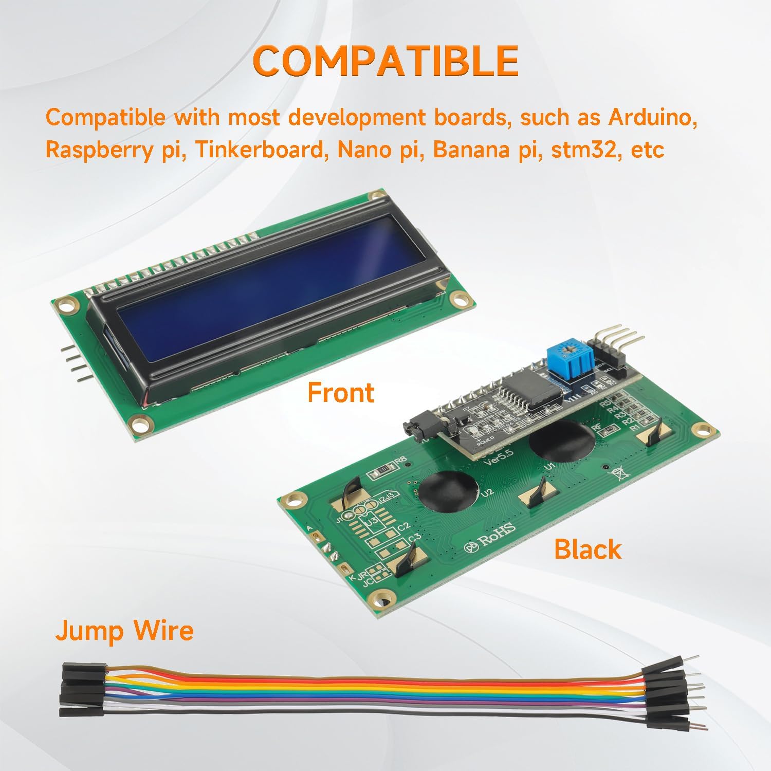
Figure 5: Examples of development boards compatible with the I2C LCD module, including Arduino and Raspberry Pi.
9. Applications
This versatile LCD module can be utilized in a wide array of electronic projects and applications, including but not limited to:
- Internet of Things (IoT) devices for displaying sensor data or status.
- Educational and school electronics projects.
- Smart building automation systems.
- Maker DIY projects requiring text output.
- Displaying letters, numbers, and custom characters.
- Real-time clock or temperature displays.

Figure 6: Visual examples of potential applications for the I2C LCD module, such as IoT, school projects, and smart systems.
10. Maintenance
To ensure the longevity and optimal performance of your LCD module, consider the following maintenance tips:
- Handling: Always handle the module by its edges to avoid touching the display surface or electronic components.
- Cleaning: Use a soft, dry, lint-free cloth to gently clean the display surface. Avoid abrasive cleaners or solvents.
- Storage: Store the module in a dry, anti-static environment, away from direct sunlight and extreme temperatures.
- Power Supply: Ensure a stable 5V power supply. Incorrect voltage can damage the module.
11. Troubleshooting
If you encounter issues with your LCD module, refer to the following common problems and solutions:
- No Display/Blank Screen: Check power connections (VCC, GND). Adjust the contrast potentiometer. Verify the I2C address in your code. Ensure the backlight jumper is in place if backlight is desired.
- Garbled Characters: Double-check wiring, especially SDA and SCL. Confirm the correct I2C address and LCD initialization parameters (e.g., number of columns and rows).
- Backlight Not Working: Ensure the backlight jumper is connected. Check power supply. If software controlled, verify the backlight function call in your code.
- Display Too Dim/Bright: Adjust the contrast potentiometer using a small screwdriver.
- Module Not Detected by I2C Scanner: Verify all four wires (GND, VCC, SDA, SCL) are correctly connected. Ensure the module is powered. Try a different I2C address if known.
12. Warranty and Support
Specific warranty information for this product is not provided in this manual. For any technical support, warranty claims, or further inquiries, please contact the seller or manufacturer directly through your purchase platform.