1. Introduction
Thank you for choosing the KATOOL ME-B600 Wheel Balancer Machine. This heavy-duty tire balancer is designed for precise wheel balancing in home garages and professional shop environments. It features a robust steel body, high-precision sensors, and a powerful 110V motor to ensure stable and accurate balancing results. This manual provides essential information for the safe and efficient operation, maintenance, and troubleshooting of your ME-B600 wheel balancer.
Please read this manual thoroughly before operating the machine to ensure proper usage and to prevent damage or injury.
2. Safety Information
Always prioritize safety when operating any machinery. Adhere to the following safety guidelines:
- Read and understand all instructions in this manual before operation.
- Ensure the machine is connected to a properly grounded 110V, 60Hz, 1ph power supply.
- Operate the balancer on a stable, level, and non-slip surface.
- Keep hands, hair, and loose clothing away from moving parts during operation.
- Do not attempt to balance wheels exceeding the maximum weight capacity of 143 lbs or diameter of 50 inches.
- Only trained and authorized personnel should operate and maintain the machine.
- Wear appropriate personal protective equipment (PPE), such as safety glasses and gloves.
- Disconnect power before performing any maintenance or repairs.
- Do not bypass any safety features or interlocks.
3. Product Overview
The KATOOL ME-B600 is engineered for precision and durability, offering a reliable solution for tire balancing needs.
Key Features:
- Robust Construction: Body made from thick steel with solid welding for high strength and minimal vibration.
- High Precision Sensor: All-in-one pressure sensor design ensures stable and accurate readings.
- Powerful Motor: Top-level motor with pure copper winding (0.34hp, 110V) provides ample power, fast heat dissipation, and extended lifespan.
- Versatile Balancing Modes: Supports various balance modes to suit different rim types for precise balancing.
- User-Friendly Interface: Built-in fault diagnosis and self-calibration program with a large screen for easier operation.
- Enhanced Stability: Features an extension point to prevent tipping when handling larger tires.
Components and Design:
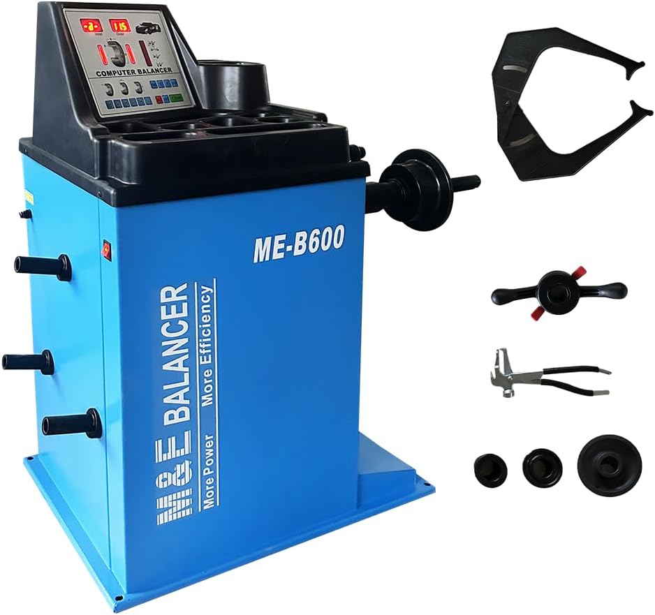
Figure 3.1: The KATOOL ME-B600 Wheel Balancer Machine, showcasing its main unit and various included accessories such as the wheel guard, mounting cones, and measuring tools.

Figure 3.2: Illustration of the product's advantages, highlighting the strict workmanship details for precision and the large, user-friendly screen for easy operation.
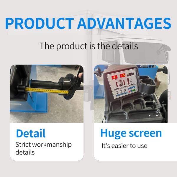
Figure 3.3: A close-up view of the powerful 110V motor, emphasizing its strong motivation and low noise operation, crucial for efficient balancing.
4. Setup
4.1 Unpacking
Carefully remove the wheel balancer and all accessories from the packaging. Inspect all components for any signs of damage during transit. Retain packaging materials for future transport or storage.
4.2 Placement
Position the ME-B600 on a firm, level, and stable concrete floor capable of supporting the machine's weight (198.4 lbs) plus the maximum wheel weight. Ensure adequate space around the machine for safe operation and maintenance.
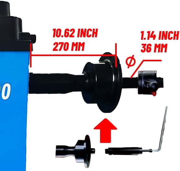
Figure 4.1: The extension point located at the base of the balancer, designed to provide additional stability and prevent the machine from tipping over, especially when mounting or balancing larger and heavier tires.
4.3 Power Connection
Connect the power cord to a dedicated 110V, 60Hz, single-phase (1ph) grounded electrical outlet. Ensure the circuit can handle the machine's power requirements (0.34hp motor). Do not use extension cords unless absolutely necessary, and if so, ensure they are heavy-duty and properly rated for the machine's power draw.
5. Operating Instructions
5.1 Mounting the Wheel
Proper wheel mounting is crucial for accurate balancing.
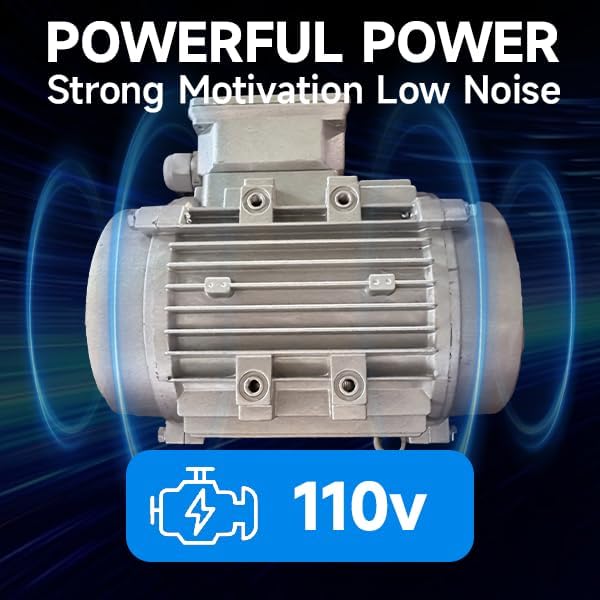
Figure 5.1: A wheel being carefully mounted onto the balancer's shaft, ensuring it is centered and securely fastened before the balancing process begins.
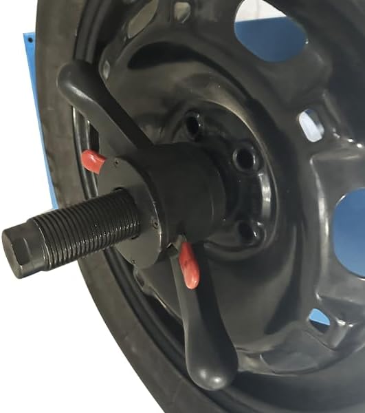
Figure 5.2: Demonstration of the reverse fitting method for mounting certain types of wheels, providing flexibility for various rim designs.
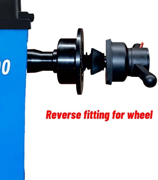
Figure 5.3: Detailed illustration of the balancer's shaft dimensions, indicating a length of 10.62 inches (270 mm) and a diameter of 1.14 inches (36 mm), important for proper wheel fitment.
- Clean the wheel and rim thoroughly to remove any dirt or debris.
- Select the appropriate mounting cone and pressure cup for the wheel's center bore.
- Slide the wheel onto the balancer shaft, ensuring it sits flush against the mounting flange.
- Secure the wheel firmly using the quick-release nut or wing nut, ensuring no wobble.
5.2 Basic Balancing Procedure
- Input the wheel's rim diameter (10"-26"), rim width (1.5"-20"), and distance from the machine using the control panel.
- Close the wheel guard (if equipped) or ensure the area is clear.
- Press the START button. The machine will spin the wheel for 6-9 seconds.
- The display will show the required weight and its location on both the inner and outer sides of the rim.
- Apply the indicated balance weights to the specified locations on the rim.
- Spin the wheel again to verify the balance. Repeat if necessary until the display shows zero or minimal imbalance.
5.3 Understanding Unbalanced Wheels
An unbalanced wheel can lead to various issues, impacting vehicle performance and safety. The ME-B600 helps mitigate these problems.
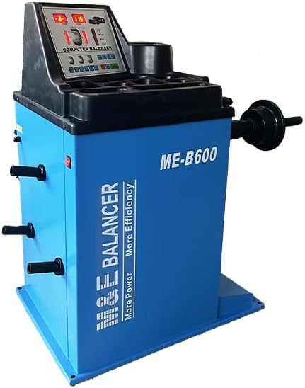
Figure 5.4: Visual representation of common issues caused by unbalanced wheels, including steering wheel shakes, vehicle resonance, uneven tire wear, and potential shock absorber damage.
6. Maintenance
Regular maintenance ensures the longevity and accuracy of your ME-B600 wheel balancer.
- Cleaning: Keep the machine clean, especially the shaft and sensor areas, to prevent debris from affecting accuracy. Use a soft, dry cloth.
- Calibration: The machine features a built-in self-calibration program. Perform calibration periodically or if you suspect accuracy issues. Refer to the on-screen instructions for double-side calibration.
- Inspection: Regularly inspect all cables, connections, and moving parts for wear or damage. Check for any loose fasteners and tighten as necessary.
- Lubrication: Consult the technical diagram for any points requiring lubrication and apply appropriate grease as needed.
7. Troubleshooting
This section addresses common issues you might encounter with your ME-B600 wheel balancer.
| Problem | Possible Cause | Solution |
|---|---|---|
| Machine does not power on | No power supply; tripped breaker; faulty power cord. | Check power connection, wall outlet, and circuit breaker. Inspect power cord for damage. |
| Inaccurate balancing results | Improper wheel mounting; dirty shaft/sensor; machine needs calibration; incorrect input parameters. | Ensure wheel is mounted correctly and securely. Clean shaft and sensor. Perform self-calibration. Verify input parameters (rim diameter, width, distance). |
| Excessive vibration during spin | Unstable machine placement; damaged wheel/tire; loose components. | Ensure machine is on a level, stable surface. Inspect wheel/tire for damage. Check for loose bolts or components. |
| Display shows error code | Internal fault; sensor issue. | Refer to the machine's built-in fault diagnosis system. If persistent, contact customer support. |
| Operation is difficult / confusing | Lack of familiarity with controls; unclear instructions. | Review this manual, especially the 'Operating Instructions' section. Utilize the large screen and built-in programs for guidance. Practice with non-critical wheels. |
8. Specifications
Detailed technical specifications for the KATOOL ME-B600 Wheel Balancer Machine:
| Parameter | Value |
|---|---|
| Model | ME-B600 |
| RIM Diameter Capacity | 10" - 26" |
| RIM Width Capacity | 1.5" - 20" |
| MAX. Wheel Diameter | 50" |
| MAX. Wheel Weight | 143 lbs (65 kg) |
| Motor | 110V, 60Hz, 1ph, 0.34hp |
| Cycle Time | 6 ~ 9 seconds |
| Product Weight | 198.4 lbs (90 kg) |
| Product Dimensions (L x W x H) | 25.2"~49.21"~39.76" (approx. 40 x 25 x 35 inches) |
| Body Material | Thickness Steel |
| Sensor Design | All-in-one pressure sensor |
| Calibration | Built-in fault diagnosis and self-calibration program (double side calibration) |
9. Warranty and Support
KATOOL stands behind the quality of its products. For specific warranty terms and conditions, please refer to the warranty card included with your purchase or visit the official KATOOL website. Keep your proof of purchase for warranty claims.
For technical support, parts, or service inquiries, please contact KATOOL customer service. When contacting support, please have your model number (ME-B600) and purchase date ready.
KATOOL Customer Support:
Please refer to your purchase documentation or the KATOOL official website for the most current contact information.


